

electric and magnetic fields, one can solve for the σ and π components of the
transmitted and reflected electric fields (Appendix E).
For synchrotron X-ray experiments, the most relevant form of these equations is
for the case with radiation traveling from the vacuum with index of refraction unity
to an absorbing medium with a complex index of refraction ñ. The details are
summarized in Appendix E, so here we will concentrate on the results.
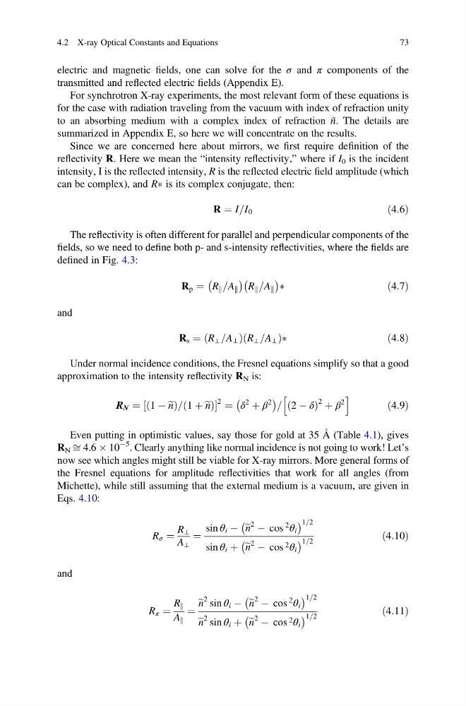
Since we are concerned here about mirrors, we first require definition of the
reflectivity R. Here we mean the “intensity reflectivity,” where if I 0 is the incident
intensity, I is the reflected intensity, R is the reflected electric field amplitude (which
can be complex), and RÃ is its complex conjugate, then:
R ¼ I=I 0
ð4:6Þ
The reflectivity is often different for parallel and perpendicular components of the
fields, so we need to define both p- and s-intensity reflectivities, where the fields are
defined in Fig. 4.3:
R p ¼ R k =A k
À
Á
R k =A k
À
Á
Ã
ð 4:7Þ
and
R s ¼ R ⊥ =A ⊥
ð
ÞR ⊥ =A ⊥
ð
ÞÃ
ð4:8Þ
Under normal incidence conditions, the Fresnel equations simplify so that a good
approximation to the intensity reflectivity R N is:
R N ¼ 1 À e n
ð
Þ= 1 þ e n
ð
Þ
½
2 ¼ δ
2
þ β
2
À
Á = 2 À δ
ð
Þ
2 þ β
2
h
i
ð4:9Þ
Even putting in optimistic values, say those for gold at 35 Å (Table 4.1), gives
R N ffi 4.6 Â 10
À5 . Clearly anything like normal incidence is not going to work! Let’s
now see which angles might still be viable for X-ray mirrors. More general forms of
the Fresnel equations for amplitude reflectivities that work for all angles (from
Michette), while still assuming that the external medium is a vacuum, are given in
Eqs. 4.10:
R σ ¼
R ⊥
A ⊥
¼
sin θ i À e n
2 À cos
2
θ i
À
Á 1=2
sin θ i þ e n
2 À cos 2 θ i
À
Á 1=2
ð4:10Þ
and
R π ¼
R k
A k
¼
e n
2 sin θ i À e n
2 À cos
2
θ i
À
Á 1=2
e n
2 sin θ i þ e n
2 À cos 2 θ i
À
Á 1=2
ð4:11Þ
4.2 X-ray Optical Constants and Equations
73
transmitted and reflected electric fields (Appendix E).
For synchrotron X-ray experiments, the most relevant form of these equations is
for the case with radiation traveling from the vacuum with index of refraction unity
to an absorbing medium with a complex index of refraction ñ. The details are
summarized in Appendix E, so here we will concentrate on the results.
Since we are concerned here about mirrors, we first require definition of the
reflectivity R. Here we mean the “intensity reflectivity,” where if I 0 is the incident
intensity, I is the reflected intensity, R is the reflected electric field amplitude (which
can be complex), and RÃ is its complex conjugate, then:
R ¼ I=I 0
ð4:6Þ
The reflectivity is often different for parallel and perpendicular components of the
fields, so we need to define both p- and s-intensity reflectivities, where the fields are
defined in Fig. 4.3:
R p ¼ R k =A k
À
Á
R k =A k
À
Á
Ã
ð 4:7Þ
and
R s ¼ R ⊥ =A ⊥
ð
ÞR ⊥ =A ⊥
ð
ÞÃ
ð4:8Þ
Under normal incidence conditions, the Fresnel equations simplify so that a good
approximation to the intensity reflectivity R N is:
R N ¼ 1 À e n
ð
Þ= 1 þ e n
ð
Þ
½
2 ¼ δ
2
þ β
2
À
Á = 2 À δ
ð
Þ
2 þ β
2
h
i
ð4:9Þ
Even putting in optimistic values, say those for gold at 35 Å (Table 4.1), gives
R N ffi 4.6 Â 10
À5 . Clearly anything like normal incidence is not going to work! Let’s
now see which angles might still be viable for X-ray mirrors. More general forms of
the Fresnel equations for amplitude reflectivities that work for all angles (from
Michette), while still assuming that the external medium is a vacuum, are given in
Eqs. 4.10:
R σ ¼
R ⊥
A ⊥
¼
sin θ i À e n
2 À cos
2
θ i
À
Á 1=2
sin θ i þ e n
2 À cos 2 θ i
À
Á 1=2
ð4:10Þ
and
R π ¼
R k
A k
¼
e n
2 sin θ i À e n
2 À cos
2
θ i
À
Á 1=2
e n
2 sin θ i þ e n
2 À cos 2 θ i
À
Á 1=2
ð4:11Þ
4.2 X-ray Optical Constants and Equations
73