

For an electromagnetic wave traveling through a material with index of refraction
ñ, the amplitude of the wave is then given by (Eq. 4.5):
A ¼ A 0 exp
À2πβx
λ
exp À2πi
nx À ct
ð
Þ
λ
"
#
ð4:5Þ
We can make some sense of the trends for δ and β by remembering that they are
related, respectively, to the scattering or absorption of photons. Both scattering and
absorption tend to increase with the number of electrons and hence with the atomic
number Z, and the general trend is also for scattering and absorption to decline with
increasing photon energy or decreasing wavelength. In Table 4.1 we can see how
different X-ray parameters are from those for the visible region.
4.2.2 The Fresnel Equations
Simple equations like the mirror equation and Snell’s law tell us about the angles for
reflection and refraction, but they don’t tell us how much power goes into the
reflected and refracted beams. The fractions of the beam that are reflected and
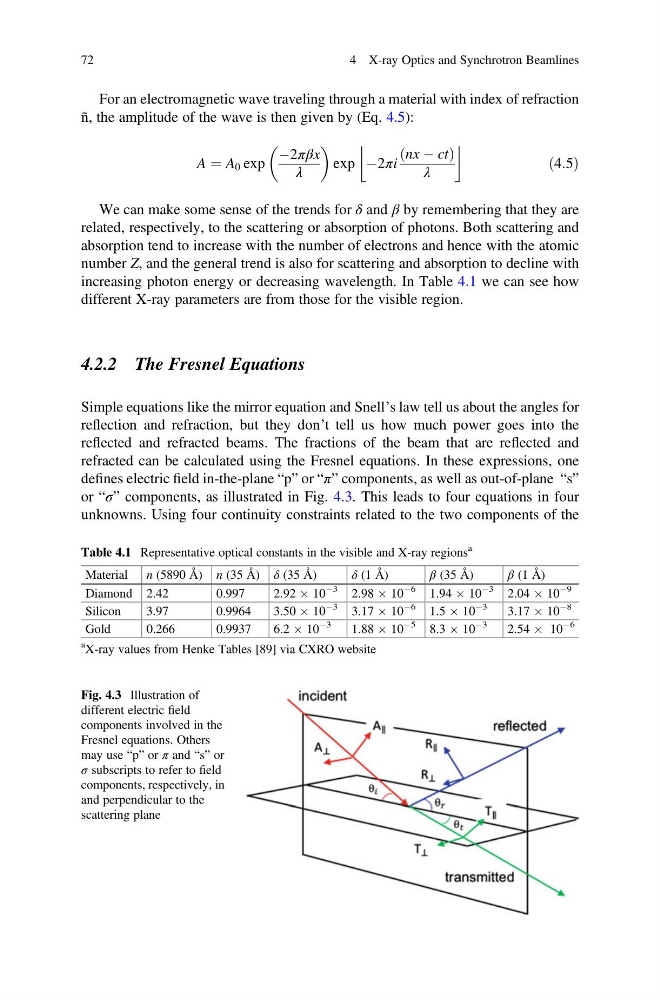
refracted can be calculated using the Fresnel equations. In these expressions, one
defines electric field in-the-plane “p” or “π” components, as well as out-of-plane “s”
or “σ” components, as illustrated in Fig. 4.3. This leads to four equations in four
unknowns. Using four continuity constraints related to the two components of the
Table 4.1 Representative optical constants in the visible and X-ray regions
a
Material n (5890 Å) n (35 Å) δ (35 Å)
δ (1 Å)
β (35 Å)
β (1 Å)
Diamond 2.42
0.997
2.92 Â 10
À3
2.98 Â 10
À6
1.94 Â 10
À3
2.04 Â 10
À9
Silicon
3.97
0.9964
3.50 Â 10
À3
3.17 Â 10
À6
1.5 Â 10
À3
3.17 Â 10
À8
Gold
0.266
0.9937
6.2 Â 10
À3
1.88 Â 10
À5
8.3 Â 10
À3
2.54 Â 10
À6
a X-ray values from Henke Tables [89] via CXRO website
Fig. 4.3 Illustration of
different electric field
components involved in the
Fresnel equations. Others
may use “p” or π and “s” or
σ subscripts to refer to field
components, respectively, in
and perpendicular to the
scattering plane
72
4 X-ray Optics and Synchrotron Beamlines
ñ, the amplitude of the wave is then given by (Eq. 4.5):
A ¼ A 0 exp
À2πβx
λ
exp À2πi
nx À ct
ð
Þ
λ
"
#
ð4:5Þ
We can make some sense of the trends for δ and β by remembering that they are
related, respectively, to the scattering or absorption of photons. Both scattering and
absorption tend to increase with the number of electrons and hence with the atomic
number Z, and the general trend is also for scattering and absorption to decline with
increasing photon energy or decreasing wavelength. In Table 4.1 we can see how
different X-ray parameters are from those for the visible region.
4.2.2 The Fresnel Equations
Simple equations like the mirror equation and Snell’s law tell us about the angles for
reflection and refraction, but they don’t tell us how much power goes into the
reflected and refracted beams. The fractions of the beam that are reflected and
refracted can be calculated using the Fresnel equations. In these expressions, one
defines electric field in-the-plane “p” or “π” components, as well as out-of-plane “s”
or “σ” components, as illustrated in Fig. 4.3. This leads to four equations in four
unknowns. Using four continuity constraints related to the two components of the
Table 4.1 Representative optical constants in the visible and X-ray regions
a
Material n (5890 Å) n (35 Å) δ (35 Å)
δ (1 Å)
β (35 Å)
β (1 Å)
Diamond 2.42
0.997
2.92 Â 10
À3
2.98 Â 10
À6
1.94 Â 10
À3
2.04 Â 10
À9
Silicon
3.97
0.9964
3.50 Â 10
À3
3.17 Â 10
À6
1.5 Â 10
À3
3.17 Â 10
À8
Gold
0.266
0.9937
6.2 Â 10
À3
1.88 Â 10
À5
8.3 Â 10
À3
2.54 Â 10
À6
a X-ray values from Henke Tables [89] via CXRO website
Fig. 4.3 Illustration of
different electric field
components involved in the
Fresnel equations. Others
may use “p” or π and “s” or
σ subscripts to refer to field
components, respectively, in
and perpendicular to the
scattering plane
72
4 X-ray Optics and Synchrotron Beamlines