

3.7.7 Combined Effects of Finite N, Emittance, and Solid
Angle
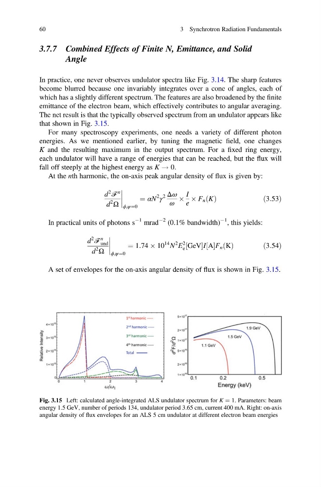
In practice, one never observes undulator spectra like Fig. 3.14. The sharp features
become blurred because one invariably integrates over a cone of angles, each of
which has a slightly different spectrum. The features are also broadened by the finite
emittance of the electron beam, which effectively contributes to angular averaging.
The net result is that the typically observed spectrum from an undulator appears like
that shown in Fig. 3.15.
For many spectroscopy experiments, one needs a variety of different photon
energies. As we mentioned earlier, by tuning the magnetic field, one changes
K and the resulting maximum in the output spectrum. For a fixed ring energy,
each undulator will have a range of energies that can be reached, but the flux will
fall off steeply at the highest energy as K ! 0.
At the nth harmonic, the on-axis peak angular density of flux is given by:
d
2
ℱ
n
d
2
Ω
ϕ,ψ¼0
¼ αN
2
γ
2 Δω
ω
Â
I
e
 F n K
ð Þ
ð3:53Þ
In practical units of photons s
À1 mrad
À2 (0.1% bandwidth)
À1 , this yields:
d
2
ℱ
n
und
d
2
Ω
ϕ,ψ¼0
¼ 1:74 Â 10
14 N
2 E
2
e GeV
½
I A
½ F n K
ð Þ
ð3:54Þ
A set of envelopes for the on-axis angular density of flux is shown in Fig. 3.15.
Fig. 3.15 Left: calculated angle-integrated ALS undulator spectrum for K ¼ 1. Parameters: beam
energy 1.5 GeV, number of periods 134, undulator period 3.65 cm, current 400 mA. Right: on-axis
angular density of flux envelopes for an ALS 5 cm undulator at different electron beam energies
60
3 Synchrotron Radiation Fundamentals
Angle
In practice, one never observes undulator spectra like Fig. 3.14. The sharp features
become blurred because one invariably integrates over a cone of angles, each of
which has a slightly different spectrum. The features are also broadened by the finite
emittance of the electron beam, which effectively contributes to angular averaging.
The net result is that the typically observed spectrum from an undulator appears like
that shown in Fig. 3.15.
For many spectroscopy experiments, one needs a variety of different photon
energies. As we mentioned earlier, by tuning the magnetic field, one changes
K and the resulting maximum in the output spectrum. For a fixed ring energy,
each undulator will have a range of energies that can be reached, but the flux will
fall off steeply at the highest energy as K ! 0.
At the nth harmonic, the on-axis peak angular density of flux is given by:
d
2
ℱ
n
d
2
Ω
ϕ,ψ¼0
¼ αN
2
γ
2 Δω
ω
Â
I
e
 F n K
ð Þ
ð3:53Þ
In practical units of photons s
À1 mrad
À2 (0.1% bandwidth)
À1 , this yields:
d
2
ℱ
n
und
d
2
Ω
ϕ,ψ¼0
¼ 1:74 Â 10
14 N
2 E
2
e GeV
½
I A
½ F n K
ð Þ
ð3:54Þ
A set of envelopes for the on-axis angular density of flux is shown in Fig. 3.15.
Fig. 3.15 Left: calculated angle-integrated ALS undulator spectrum for K ¼ 1. Parameters: beam
energy 1.5 GeV, number of periods 134, undulator period 3.65 cm, current 400 mA. Right: on-axis
angular density of flux envelopes for an ALS 5 cm undulator at different electron beam energies
60
3 Synchrotron Radiation Fundamentals