

3.7.2 Integrated Power
Our general expression for the power from an insertion device was Eq. 3.30. In a
planar undulator, integrating the square of the sinusoidal field leads to:
P kW
½ ¼ 0:63E
2
e GeV
½
I A
½ B
2
0 T
½ L m
½
ð3:45Þ
3.7.3 Harmonics
For very small K-values and very close to on-axis observation, only the fundamental
energy is observed. As K increases, higher harmonics begin to appear. If observed
strictly on-axis, symmetry dictates that only odd harmonics have significant intensity. (For even harmonics, the radiation from one pole is out of phase with that from
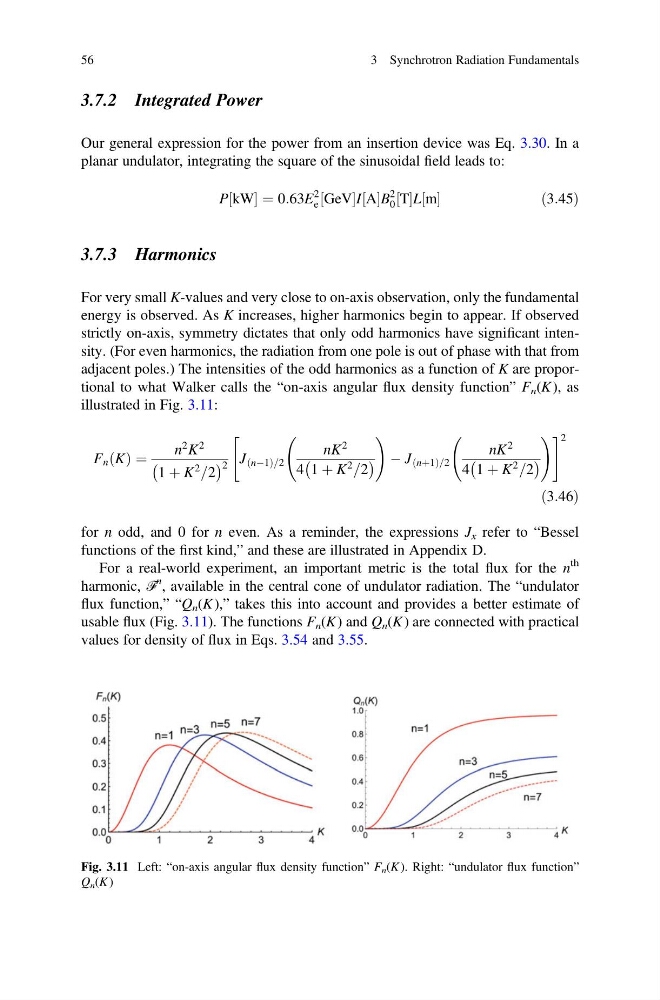
adjacent poles.) The intensities of the odd harmonics as a function of K are proportional to what Walker calls the “on-axis angular flux density function” F n (K ), as
illustrated in Fig. 3.11:
F n K
ð Þ ¼
n
2 K
2
1 þ K
2
=2
À
Á 2 J nÀ1
ð
Þ=2
nK
2
4 1 þ K
2
=2
À
Á
!
À J nþ1
ð
Þ=2
nK
2
4 1 þ K
2
=2
À
Á
!
"
# 2
ð3:46Þ
for n odd, and 0 for n even. As a reminder, the expressions J x refer to “Bessel
functions of the first kind,” and these are illustrated in Appendix D.
For a real-world experiment, an important metric is the total flux for the n
th
harmonic, ℱ
n , available in the central cone of undulator radiation. The “undulator
flux function,” “Q n (K ),” takes this into account and provides a better estimate of
usable flux (Fig. 3.11). The functions F n (K ) and Q n (K) are connected with practical
values for density of flux in Eqs. 3.54 and 3.55.
Fig. 3.11 Left: “on-axis angular flux density function” F n (K ). Right: “undulator flux function”
Q n (K )
56
3 Synchrotron Radiation Fundamentals
Our general expression for the power from an insertion device was Eq. 3.30. In a
planar undulator, integrating the square of the sinusoidal field leads to:
P kW
½ ¼ 0:63E
2
e GeV
½
I A
½ B
2
0 T
½ L m
½
ð3:45Þ
3.7.3 Harmonics
For very small K-values and very close to on-axis observation, only the fundamental
energy is observed. As K increases, higher harmonics begin to appear. If observed
strictly on-axis, symmetry dictates that only odd harmonics have significant intensity. (For even harmonics, the radiation from one pole is out of phase with that from
adjacent poles.) The intensities of the odd harmonics as a function of K are proportional to what Walker calls the “on-axis angular flux density function” F n (K ), as
illustrated in Fig. 3.11:
F n K
ð Þ ¼
n
2 K
2
1 þ K
2
=2
À
Á 2 J nÀ1
ð
Þ=2
nK
2
4 1 þ K
2
=2
À
Á
!
À J nþ1
ð
Þ=2
nK
2
4 1 þ K
2
=2
À
Á
!
"
# 2
ð3:46Þ
for n odd, and 0 for n even. As a reminder, the expressions J x refer to “Bessel
functions of the first kind,” and these are illustrated in Appendix D.
For a real-world experiment, an important metric is the total flux for the n
th
harmonic, ℱ
n , available in the central cone of undulator radiation. The “undulator
flux function,” “Q n (K ),” takes this into account and provides a better estimate of
usable flux (Fig. 3.11). The functions F n (K ) and Q n (K) are connected with practical
values for density of flux in Eqs. 3.54 and 3.55.
Fig. 3.11 Left: “on-axis angular flux density function” F n (K ). Right: “undulator flux function”
Q n (K )
56
3 Synchrotron Radiation Fundamentals