

radiated by a magnetic device of length L and field B(s) in Tesla for a ring current of
I amperes of electrons of energy E in GeV [74]:
P kW
½ ¼ 1:265E
2
e GeV
½
I A
½
Z L
0
B
2 s
ð Þ T
½ ds
ð3:30Þ
The same equation (Eq. 3.30) applies to any magnetic structure—bend magnet,
wiggler, or undulator. Since the ring energy is pretty much fixed, to generate more
radiated power, there are only two options: (a) increase the magnetic field and
(b) increase the length over which the magnetic field operates. If total power radiated
were the best metric for the quality of a synchrotron source, then this formula would
argue for long and very high field wigglers. However, for many spectroscopy
experiments, spectral brightness is more important, and a third option
(c) increasing the number of poles becomes more important. We will develop this
further in the section on undulators.
3.4.1 K: The Deflection Parameter
The properties of undulators and wigglers lie on a continuum, characterized by the
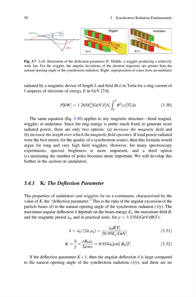
value of K, the “deflection parameter.” This is the ratio of the angular excursion of the
particle beam (δ) to the natural opening angle of the synchrotron radiation (1/γ). The
maximum angular deflection δ depends on the beam energy E e , the maximum field B,
and the magnetic period λ 0 , and in practical units, for ρ ¼ 3.335E(GeV)/B(T):
δ ¼ λ 0 = 2π ρ 0
ð
Þ¼
λ 0 B T
½
20:95E e GeV
½
ð3:31Þ
K ¼
δ
γ
¼
eB 0 λ 0
2π mc
¼ 0:934λ 0 cm
½ B 0 T
½
ð3:32Þ
If the deflection parameter K » 1, then the angular deflection δ is large compared
to the natural opening angle of the synchrotron radiation (1/γ), and there are no
Fig. 3.7 Left: illustration of the deflection parameter K. Middle: a wiggler producing a relatively
wide fan. For the wiggler, the angular deviations of the electron trajectory are greater than the
natural opening angle of the synchrotron radiation. Right: superposition of cones from an undulator
50
3 Synchrotron Radiation Fundamentals
I amperes of electrons of energy E in GeV [74]:
P kW
½ ¼ 1:265E
2
e GeV
½
I A
½
Z L
0
B
2 s
ð Þ T
½ ds
ð3:30Þ
The same equation (Eq. 3.30) applies to any magnetic structure—bend magnet,
wiggler, or undulator. Since the ring energy is pretty much fixed, to generate more
radiated power, there are only two options: (a) increase the magnetic field and
(b) increase the length over which the magnetic field operates. If total power radiated
were the best metric for the quality of a synchrotron source, then this formula would
argue for long and very high field wigglers. However, for many spectroscopy
experiments, spectral brightness is more important, and a third option
(c) increasing the number of poles becomes more important. We will develop this
further in the section on undulators.
3.4.1 K: The Deflection Parameter
The properties of undulators and wigglers lie on a continuum, characterized by the
value of K, the “deflection parameter.” This is the ratio of the angular excursion of the
particle beam (δ) to the natural opening angle of the synchrotron radiation (1/γ). The
maximum angular deflection δ depends on the beam energy E e , the maximum field B,
and the magnetic period λ 0 , and in practical units, for ρ ¼ 3.335E(GeV)/B(T):
δ ¼ λ 0 = 2π ρ 0
ð
Þ¼
λ 0 B T
½
20:95E e GeV
½
ð3:31Þ
K ¼
δ
γ
¼
eB 0 λ 0
2π mc
¼ 0:934λ 0 cm
½ B 0 T
½
ð3:32Þ
If the deflection parameter K » 1, then the angular deflection δ is large compared
to the natural opening angle of the synchrotron radiation (1/γ), and there are no
Fig. 3.7 Left: illustration of the deflection parameter K. Middle: a wiggler producing a relatively
wide fan. For the wiggler, the angular deviations of the electron trajectory are greater than the
natural opening angle of the synchrotron radiation. Right: superposition of cones from an undulator
50
3 Synchrotron Radiation Fundamentals