

For some experiments (such as XMCD that we discuss in Chap. 7), one needs a
circularly polarized X-ray beam. As you might expect, one way to obtain circular
polarization is to have the particle beam rotate as it travels, yielding a helical
trajectory. To accomplish this, ID designers use the same basic tools as with
horizontal insertion devices: electromagnets, permanent magnets, or
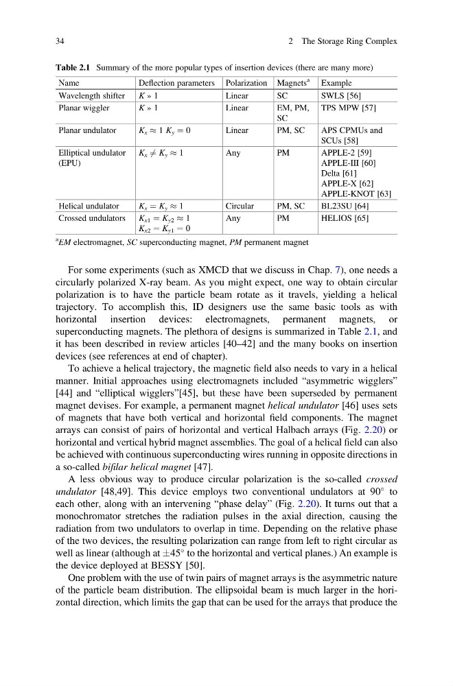
superconducting magnets. The plethora of designs is summarized in Table 2.1, and
it has been described in review articles [40–42] and the many books on insertion
devices (see references at end of chapter).
To achieve a helical trajectory, the magnetic field also needs to vary in a helical
manner. Initial approaches using electromagnets included “asymmetric wigglers”
[44] and “elliptical wigglers”[45], but these have been superseded by permanent
magnet devises. For example, a permanent magnet helical undulator [46] uses sets
of magnets that have both vertical and horizontal field components. The magnet
arrays can consist of pairs of horizontal and vertical Halbach arrays (Fig. 2.20) or
horizontal and vertical hybrid magnet assemblies. The goal of a helical field can also
be achieved with continuous superconducting wires running in opposite directions in
a so-called bifilar helical magnet [47].
A less obvious way to produce circular polarization is the so-called crossed
undulator [48,49]. This device employs two conventional undulators at 90
to
each other, along with an intervening “phase delay” (Fig. 2.20). It turns out that a
monochromator stretches the radiation pulses in the axial direction, causing the
radiation from two undulators to overlap in time. Depending on the relative phase
of the two devices, the resulting polarization can range from left to right circular as
well as linear (although at Æ45
to the horizontal and vertical planes.) An example is
the device deployed at BESSY [50].
One problem with the use of twin pairs of magnet arrays is the asymmetric nature
of the particle beam distribution. The ellipsoidal beam is much larger in the horizontal direction, which limits the gap that can be used for the arrays that produce the
Table 2.1 Summary of the more popular types of insertion devices (there are many more)
Name
Deflection parameters Polarization Magnets
a
Example
Wavelength shifter
K » 1
Linear
SC
SWLS [56]
Planar wiggler
K » 1
Linear
EM, PM,
SC
TPS MPW [57]
Planar undulator
K x % 1 K y ¼ 0
Linear
PM, SC
APS CPMUs and
SCUs [58]
Elliptical undulator
(EPU)
K x 6 ¼ K y % 1
Any
PM
APPLE-2 [59]
APPLE-III [60]
Delta [61]
APPLE-X [62]
APPLE-KNOT [63]
Helical undulator
K x ¼ K y % 1
Circular
PM, SC
BL23SU [64]
Crossed undulators
K x1 ¼ K y2 % 1
K x2 ¼ K y1 ¼ 0
Any
PM
HELIOS [65]
a EM electromagnet, SC superconducting magnet, PM permanent magnet
34
2 The Storage Ring Complex
circularly polarized X-ray beam. As you might expect, one way to obtain circular
polarization is to have the particle beam rotate as it travels, yielding a helical
trajectory. To accomplish this, ID designers use the same basic tools as with
horizontal insertion devices: electromagnets, permanent magnets, or
superconducting magnets. The plethora of designs is summarized in Table 2.1, and
it has been described in review articles [40–42] and the many books on insertion
devices (see references at end of chapter).
To achieve a helical trajectory, the magnetic field also needs to vary in a helical
manner. Initial approaches using electromagnets included “asymmetric wigglers”
[44] and “elliptical wigglers”[45], but these have been superseded by permanent
magnet devises. For example, a permanent magnet helical undulator [46] uses sets
of magnets that have both vertical and horizontal field components. The magnet
arrays can consist of pairs of horizontal and vertical Halbach arrays (Fig. 2.20) or
horizontal and vertical hybrid magnet assemblies. The goal of a helical field can also
be achieved with continuous superconducting wires running in opposite directions in
a so-called bifilar helical magnet [47].
A less obvious way to produce circular polarization is the so-called crossed
undulator [48,49]. This device employs two conventional undulators at 90
to
each other, along with an intervening “phase delay” (Fig. 2.20). It turns out that a
monochromator stretches the radiation pulses in the axial direction, causing the
radiation from two undulators to overlap in time. Depending on the relative phase
of the two devices, the resulting polarization can range from left to right circular as
well as linear (although at Æ45
to the horizontal and vertical planes.) An example is
the device deployed at BESSY [50].
One problem with the use of twin pairs of magnet arrays is the asymmetric nature
of the particle beam distribution. The ellipsoidal beam is much larger in the horizontal direction, which limits the gap that can be used for the arrays that produce the
Table 2.1 Summary of the more popular types of insertion devices (there are many more)
Name
Deflection parameters Polarization Magnets
a
Example
Wavelength shifter
K » 1
Linear
SC
SWLS [56]
Planar wiggler
K » 1
Linear
EM, PM,
SC
TPS MPW [57]
Planar undulator
K x % 1 K y ¼ 0
Linear
PM, SC
APS CPMUs and
SCUs [58]
Elliptical undulator
(EPU)
K x 6 ¼ K y % 1
Any
PM
APPLE-2 [59]
APPLE-III [60]
Delta [61]
APPLE-X [62]
APPLE-KNOT [63]
Helical undulator
K x ¼ K y % 1
Circular
PM, SC
BL23SU [64]
Crossed undulators
K x1 ¼ K y2 % 1
K x2 ¼ K y1 ¼ 0
Any
PM
HELIOS [65]
a EM electromagnet, SC superconducting magnet, PM permanent magnet
34
2 The Storage Ring Complex