

horizontal magnet field. The crossed undulator approach, although elegant, takes up
twice as much precious real estate in the storage ring straight section. However, for
free-electron laser facilities (Chap. 12) where space is more plentiful and the bunch
is smaller and more symmetrical, the crossed undulator approach is making a
comeback [51,52].
For storage ring sources, the most popular approach has been the so-called
APPLE-2 (Advanced Planar Polarizer Emitter-2) invented by Sasaki [53]. In an
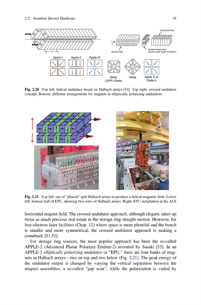
APPLE-2 elliptically polarizing undulator or “EPU,” there are four banks of magnets in Halbach arrays—two on top and two below (Fig. 2.21). The peak energy of
the undulator output is changed by varying the vertical separation between the
magnet assemblies, a so-called “gap scan”, while the polarization is varied by
Fig. 2.20 Top left: helical undulator based on Halbach arrays [43]. Top right: crossed undulator
concept. Bottom: different arrangements for magnets in elliptically polarizing undulators
Fig. 2.21 Top left: use of “phased” split Halbach arrays to produce a helical magnetic field. Lower
left: bottom half of EPU, showing two rows of Halbach arrays. Right: EPU installation at the ALS
2.5 Insertion Device Hardware
35
twice as much precious real estate in the storage ring straight section. However, for
free-electron laser facilities (Chap. 12) where space is more plentiful and the bunch
is smaller and more symmetrical, the crossed undulator approach is making a
comeback [51,52].
For storage ring sources, the most popular approach has been the so-called
APPLE-2 (Advanced Planar Polarizer Emitter-2) invented by Sasaki [53]. In an
APPLE-2 elliptically polarizing undulator or “EPU,” there are four banks of magnets in Halbach arrays—two on top and two below (Fig. 2.21). The peak energy of
the undulator output is changed by varying the vertical separation between the
magnet assemblies, a so-called “gap scan”, while the polarization is varied by
Fig. 2.20 Top left: helical undulator based on Halbach arrays [43]. Top right: crossed undulator
concept. Bottom: different arrangements for magnets in elliptically polarizing undulators
Fig. 2.21 Top left: use of “phased” split Halbach arrays to produce a helical magnetic field. Lower
left: bottom half of EPU, showing two rows of Halbach arrays. Right: EPU installation at the ALS
2.5 Insertion Device Hardware
35