

From the above, it is clear that by changing the gap g between the undulator
magnets, one can tune the magnetic field that is applied to the particle beam. In the
above example, for an undulator period of 7 cm, a maximum field of ~1.2 T is
achieved at a gap of 0.6 cm.
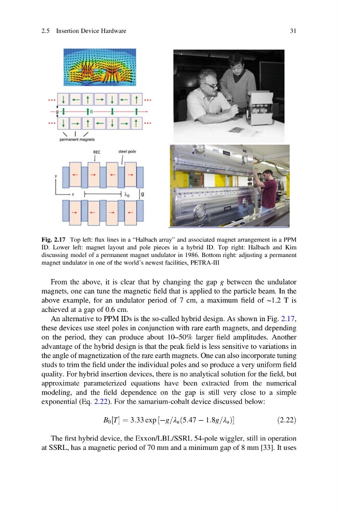
An alternative to PPM IDs is the so-called hybrid design. As shown in Fig. 2.17,
these devices use steel poles in conjunction with rare earth magnets, and depending
on the period, they can produce about 10–50% larger field amplitudes. Another
advantage of the hybrid design is that the peak field is less sensitive to variations in
the angle of magnetization of the rare earth magnets. One can also incorporate tuning
studs to trim the field under the individual poles and so produce a very uniform field
quality. For hybrid insertion devices, there is no analytical solution for the field, but
approximate parameterized equations have been extracted from the numerical
modeling, and the field dependence on the gap is still very close to a simple
exponential (Eq. 2.22). For the samarium-cobalt device discussed below:
B 0 T
½ ¼ 3:33 exp Àg=λ u 5:47 À 1:8g=λ u
ð
Þ
½
ð 2:22Þ
The first hybrid device, the Exxon/LBL/SSRL 54-pole wiggler, still in operation
at SSRL, has a magnetic period of 70 mm and a minimum gap of 8 mm [33]. It uses
Fig. 2.17 Top left: flux lines in a “Halbach array” and associated magnet arrangement in a PPM
ID. Lower left: magnet layout and pole pieces in a hybrid ID. Top right: Halbach and Kim
discussing model of a permanent magnet undulator in 1986. Bottom right: adjusting a permanent
magnet undulator in one of the world’s newest facilities, PETRA-III
2.5 Insertion Device Hardware
31
magnets, one can tune the magnetic field that is applied to the particle beam. In the
above example, for an undulator period of 7 cm, a maximum field of ~1.2 T is
achieved at a gap of 0.6 cm.
An alternative to PPM IDs is the so-called hybrid design. As shown in Fig. 2.17,
these devices use steel poles in conjunction with rare earth magnets, and depending
on the period, they can produce about 10–50% larger field amplitudes. Another
advantage of the hybrid design is that the peak field is less sensitive to variations in
the angle of magnetization of the rare earth magnets. One can also incorporate tuning
studs to trim the field under the individual poles and so produce a very uniform field
quality. For hybrid insertion devices, there is no analytical solution for the field, but
approximate parameterized equations have been extracted from the numerical
modeling, and the field dependence on the gap is still very close to a simple
exponential (Eq. 2.22). For the samarium-cobalt device discussed below:
B 0 T
½ ¼ 3:33 exp Àg=λ u 5:47 À 1:8g=λ u
ð
Þ
½
ð 2:22Þ
The first hybrid device, the Exxon/LBL/SSRL 54-pole wiggler, still in operation
at SSRL, has a magnetic period of 70 mm and a minimum gap of 8 mm [33]. It uses
Fig. 2.17 Top left: flux lines in a “Halbach array” and associated magnet arrangement in a PPM
ID. Lower left: magnet layout and pole pieces in a hybrid ID. Top right: Halbach and Kim
discussing model of a permanent magnet undulator in 1986. Bottom right: adjusting a permanent
magnet undulator in one of the world’s newest facilities, PETRA-III
2.5 Insertion Device Hardware
31