

2.5.4 Permanent Magnet Insertion Devices
To allow for production of shorter period insertion devices, the community turned to
insertion devices based on rare earth permanent magnets, using some of the same
concepts employed in the kitchen magnets on your refrigerator. The use of permanent magnets was first proposed by Klaus Halbach in 1980 [31] and implemented
soon after in the Exxon/SSRL/LBNL 54-pole wiggler in 1983 [32,33].
These “hard” (high “coercivity”) permanent magnets have the nice property that
magnetic fields for an assembly can be approximated as the linear sum of fields from
the individual magnets [30]. Although they can be arranged many different ways, for
“pure permanent magnet” (PPM) insertion devices the most common pattern is a
so-called Halbach array (Fig. 2.17), which involves a cycle of four magnets with
fields rotated by 90
from one block to the next [31].
The field in a PPM ID can be derived analytically from the “superposition
principle,” which means you can just add the fields from different blocks together.
The detailed equations depend on the type and shape of the magnetic material and
can be found elsewhere [34]. In the case of four blocks with square cross sections per
period, block height h equal to one quarter the undulator period λ u , then for a gap
g between upper and lower jaws of the device, the peak field B 0 is given by Eq. 2.21,
assuming a typical SmCo 5 remanent field of 0.9 T [34]: .
B 0 T
ð Þ ¼ 1:28 exp Àπg=λ u
ð
Þ
ð 2:21Þ
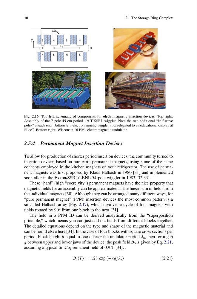
Fig. 2.16 Top left: schematic of components for electromagnetic insertion devices. Top right:
Assembly of the 7 pole 45 cm period 1.9 T SSRL wiggler. Note the two additional “half-wave
poles” at each end. Bottom left: electromagnetic wiggler now relegated to an educational display at
SLAC. Bottom right: Wisconsin “6 EM” electromagnetic undulator
30
2 The Storage Ring Complex
To allow for production of shorter period insertion devices, the community turned to
insertion devices based on rare earth permanent magnets, using some of the same
concepts employed in the kitchen magnets on your refrigerator. The use of permanent magnets was first proposed by Klaus Halbach in 1980 [31] and implemented
soon after in the Exxon/SSRL/LBNL 54-pole wiggler in 1983 [32,33].
These “hard” (high “coercivity”) permanent magnets have the nice property that
magnetic fields for an assembly can be approximated as the linear sum of fields from
the individual magnets [30]. Although they can be arranged many different ways, for
“pure permanent magnet” (PPM) insertion devices the most common pattern is a
so-called Halbach array (Fig. 2.17), which involves a cycle of four magnets with
fields rotated by 90
from one block to the next [31].
The field in a PPM ID can be derived analytically from the “superposition
principle,” which means you can just add the fields from different blocks together.
The detailed equations depend on the type and shape of the magnetic material and
can be found elsewhere [34]. In the case of four blocks with square cross sections per
period, block height h equal to one quarter the undulator period λ u , then for a gap
g between upper and lower jaws of the device, the peak field B 0 is given by Eq. 2.21,
assuming a typical SmCo 5 remanent field of 0.9 T [34]: .
B 0 T
ð Þ ¼ 1:28 exp Àπg=λ u
ð
Þ
ð 2:21Þ
Fig. 2.16 Top left: schematic of components for electromagnetic insertion devices. Top right:
Assembly of the 7 pole 45 cm period 1.9 T SSRL wiggler. Note the two additional “half-wave
poles” at each end. Bottom left: electromagnetic wiggler now relegated to an educational display at
SLAC. Bottom right: Wisconsin “6 EM” electromagnetic undulator
30
2 The Storage Ring Complex