

R ⊥
A ⊥
¼
sin θ i À e n
2 À cos
2
θ i
À
Á 1=2
sin θ i þ e n
2 À cos 2 θ i
À
Á 1=2
ðE:21Þ
T k
A k
¼
2e n sin θ i
e n
2 sin θ i þ e n À cos 2 θ i
ð
Þ
1=2
ðE:22Þ
T ⊥
A ⊥
¼
2 sin θ i
sin θ i þ e n
2 À cos 2 θ i
À
Á 1=2
ðE:23Þ
Appendix E.2: Stokes Parameters and the Polarization
Ellipse
The Stokes parameters are a way to describe the polarization of light based on
measurable observables. They were first developed by Sir George Stokes in 1852,
but only popularized about a century later. Measurement of the Stokes parameters
assumes access to 4 filters, each of which transmits 50% of the incident light under
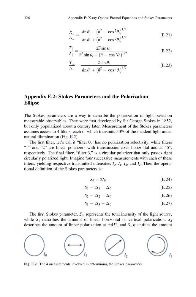
natural illumination (Fig. E.2).
The first filter, let’s call it “filter 0,” has no polarization selectivity, while filters
“1” and “2” are linear polarizers with transmission axes horizontal and at 45
,
respectively. The final filter, “filter 3,” is a circular polarizer that only passes right
circularly polarized light. Imagine four successive measurements with each of these
filters, yielding respective transmitted intensities I 0 , I 1 , I 2 , and I 3 . Then the operational definition of the Stokes parameters is:
S 0 ¼ 2I 0
ðE:24Þ
S 1 ¼ 2I 1 À 2I 0
ðE:25Þ
S 2 ¼ 2I 2 À 2I 0
ðE:26Þ
S 3 ¼ 2I 3 À 2I 0
ðE:27Þ
The first Stokes parameter, S 0 , represents the total intensity of the light source,
while S 1 describes the amount of linear horizontal or vertical polarization. S 2
describes the amount of linear polarization at Æ45
, and S 3 quantifies the amount
Fig. E.2 The 4 measurements involved in determining the Stokes parameters
326
Appendix E: X-ray Optics: Fresnel Equations and Stokes Parameters
A ⊥
¼
sin θ i À e n
2 À cos
2
θ i
À
Á 1=2
sin θ i þ e n
2 À cos 2 θ i
À
Á 1=2
ðE:21Þ
T k
A k
¼
2e n sin θ i
e n
2 sin θ i þ e n À cos 2 θ i
ð
Þ
1=2
ðE:22Þ
T ⊥
A ⊥
¼
2 sin θ i
sin θ i þ e n
2 À cos 2 θ i
À
Á 1=2
ðE:23Þ
Appendix E.2: Stokes Parameters and the Polarization
Ellipse
The Stokes parameters are a way to describe the polarization of light based on
measurable observables. They were first developed by Sir George Stokes in 1852,
but only popularized about a century later. Measurement of the Stokes parameters
assumes access to 4 filters, each of which transmits 50% of the incident light under
natural illumination (Fig. E.2).
The first filter, let’s call it “filter 0,” has no polarization selectivity, while filters
“1” and “2” are linear polarizers with transmission axes horizontal and at 45
,
respectively. The final filter, “filter 3,” is a circular polarizer that only passes right
circularly polarized light. Imagine four successive measurements with each of these
filters, yielding respective transmitted intensities I 0 , I 1 , I 2 , and I 3 . Then the operational definition of the Stokes parameters is:
S 0 ¼ 2I 0
ðE:24Þ
S 1 ¼ 2I 1 À 2I 0
ðE:25Þ
S 2 ¼ 2I 2 À 2I 0
ðE:26Þ
S 3 ¼ 2I 3 À 2I 0
ðE:27Þ
The first Stokes parameter, S 0 , represents the total intensity of the light source,
while S 1 describes the amount of linear horizontal or vertical polarization. S 2
describes the amount of linear polarization at Æ45
, and S 3 quantifies the amount
Fig. E.2 The 4 measurements involved in determining the Stokes parameters
326
Appendix E: X-ray Optics: Fresnel Equations and Stokes Parameters