

When used directly as an X-ray detector, the spatial resolution of a CCD used for
depends on the pixel size, which is on the order of 10 μm  10 μm. The maximum
pixel count rate in integrating mode depends on the highest amount of charge that
can be accommodated and the frequency with which the device can be read out.
5.7 Geiger Counters and Gas Proportional Detectors
The Geiger counter was the first device capable of detecting individual X-ray
photons. It was developed in 1908 by Geiger and Rutherford at the Cavendish lab
for recording α-particles [172], and with modifications by Geiger and Müller, it
became sensitive to gamma-rays and X-rays [173]. A “Geiger-Müller tube” is
similar to an ion chamber, but instead of flat plates, it commonly employs a
cylindrical chamber containing a noble gas and a thin wire central anode
(Fig. 5.7). As opposed to the uniform electric field in a flat plate ionization chamber,
in a cylindrical geometry with cathode inner radius b and anode wire radius a, the
magnitude of the electric field at radius r is given by:
ε r
ð Þ ¼
V
r ln
b
a
À Á
ð5:4Þ
Absorption of a photon in the gas yields an electron-ion pair. However, the
combination of a high voltage (~500 V), high electric field strength in the vicinity
of the wire anode, and reduced gas pressure (~0.1 atm) gives the free electron an
especially large acceleration and sufficient energy to ionize additional gas molecules
by collision. These additional electrons can in turn ionize additional gas molecules,
yielding a so-called Townsend avalanche of current in the vicinity of the anode wire.
Even more avalanches are produced by production and subsequent absorption of UV
photons, so that one initial X-ray can produce on the order of 10
9
–10
10 electron-ion
pairs. The process eventually stops when a space charge builds up from the relatively
motionless positive ions. Additional time, ~100 μs, is needed for these ions to reach
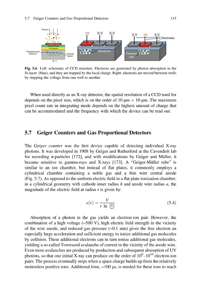
Fig. 5.6 Left: schematic of CCD structure. Electrons are generated by photon absorption in the
Si-layer (blue), and they are trapped by the local charge. Right: electrons are moved between wells
by stepping the voltage from one well to another
5.7 Geiger Counters and Gas Proportional Detectors
115
depends on the pixel size, which is on the order of 10 μm  10 μm. The maximum
pixel count rate in integrating mode depends on the highest amount of charge that
can be accommodated and the frequency with which the device can be read out.
5.7 Geiger Counters and Gas Proportional Detectors
The Geiger counter was the first device capable of detecting individual X-ray
photons. It was developed in 1908 by Geiger and Rutherford at the Cavendish lab
for recording α-particles [172], and with modifications by Geiger and Müller, it
became sensitive to gamma-rays and X-rays [173]. A “Geiger-Müller tube” is
similar to an ion chamber, but instead of flat plates, it commonly employs a
cylindrical chamber containing a noble gas and a thin wire central anode
(Fig. 5.7). As opposed to the uniform electric field in a flat plate ionization chamber,
in a cylindrical geometry with cathode inner radius b and anode wire radius a, the
magnitude of the electric field at radius r is given by:
ε r
ð Þ ¼
V
r ln
b
a
À Á
ð5:4Þ
Absorption of a photon in the gas yields an electron-ion pair. However, the
combination of a high voltage (~500 V), high electric field strength in the vicinity
of the wire anode, and reduced gas pressure (~0.1 atm) gives the free electron an
especially large acceleration and sufficient energy to ionize additional gas molecules
by collision. These additional electrons can in turn ionize additional gas molecules,
yielding a so-called Townsend avalanche of current in the vicinity of the anode wire.
Even more avalanches are produced by production and subsequent absorption of UV
photons, so that one initial X-ray can produce on the order of 10
9
–10
10 electron-ion
pairs. The process eventually stops when a space charge builds up from the relatively
motionless positive ions. Additional time, ~100 μs, is needed for these ions to reach
Fig. 5.6 Left: schematic of CCD structure. Electrons are generated by photon absorption in the
Si-layer (blue), and they are trapped by the local charge. Right: electrons are moved between wells
by stepping the voltage from one well to another
5.7 Geiger Counters and Gas Proportional Detectors
115