

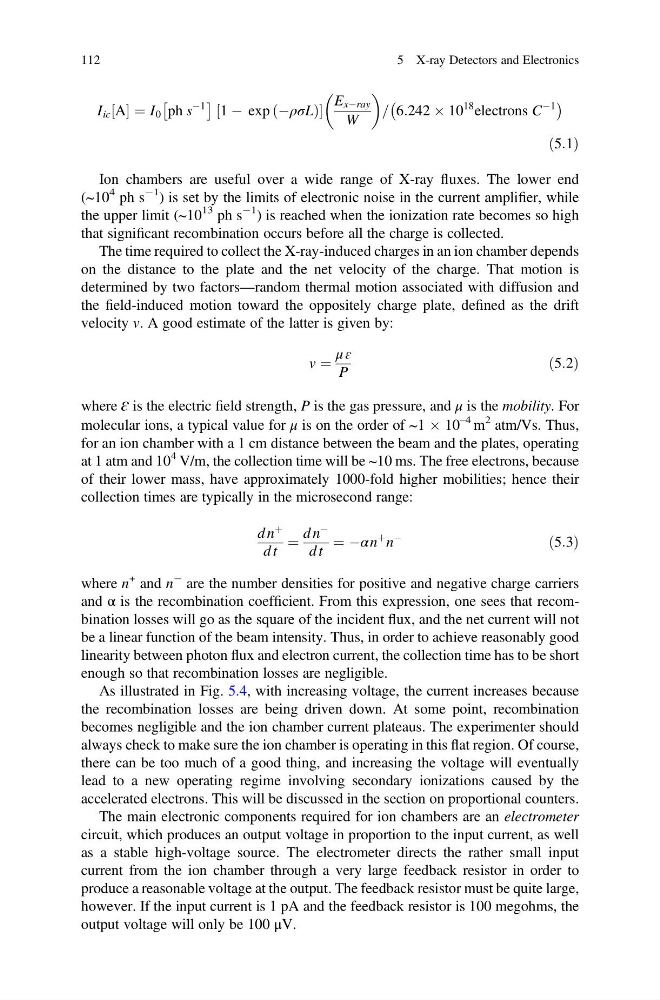
I ic A
½ ¼ I 0 ph s
À1
Â
Ã
1 À exp ÀρσL
ð
Þ
½
E xÀray
W
= 6:242 Â 10
18 electrons C
À1
À
Á
ð5:1Þ
Ion chambers are useful over a wide range of X-ray fluxes. The lower end
(~10
4 ph s
À1 ) is set by the limits of electronic noise in the current amplifier, while
the upper limit (~10
13 ph s
À1 ) is reached when the ionization rate becomes so high
that significant recombination occurs before all the charge is collected.
The time required to collect the X-ray-induced charges in an ion chamber depends
on the distance to the plate and the net velocity of the charge. That motion is
determined by two factors—random thermal motion associated with diffusion and
the field-induced motion toward the oppositely charge plate, defined as the drift
velocity v. A good estimate of the latter is given by:
v ¼
μ ɛ
P
ð5:2Þ
where ɛ is the electric field strength, P is the gas pressure, and μ is the mobility. For
molecular ions, a typical value for μ is on the order of ~1 Â 10
–4 m
2 atm/Vs. Thus,
for an ion chamber with a 1 cm distance between the beam and the plates, operating
at 1 atm and 10
4 V/m, the collection time will be ~10 ms. The free electrons, because
of their lower mass, have approximately 1000-fold higher mobilities; hence their
collection times are typically in the microsecond range:
d n
þ
d t
¼
d n
À
d t
¼ Àα n
þ n
À
ð5:3Þ
where n
+ and n
À are the number densities for positive and negative charge carriers
and α is the recombination coefficient. From this expression, one sees that recombination losses will go as the square of the incident flux, and the net current will not
be a linear function of the beam intensity. Thus, in order to achieve reasonably good
linearity between photon flux and electron current, the collection time has to be short
enough so that recombination losses are negligible.
As illustrated in Fig. 5.4, with increasing voltage, the current increases because
the recombination losses are being driven down. At some point, recombination
becomes negligible and the ion chamber current plateaus. The experimenter should
always check to make sure the ion chamber is operating in this flat region. Of course,
there can be too much of a good thing, and increasing the voltage will eventually
lead to a new operating regime involving secondary ionizations caused by the
accelerated electrons. This will be discussed in the section on proportional counters.
The main electronic components required for ion chambers are an electrometer
circuit, which produces an output voltage in proportion to the input current, as well
as a stable high-voltage source. The electrometer directs the rather small input
current from the ion chamber through a very large feedback resistor in order to
produce a reasonable voltage at the output. The feedback resistor must be quite large,
however. If the input current is 1 pA and the feedback resistor is 100 megohms, the
output voltage will only be 100 μV.
112
5 X-ray Detectors and Electronics
½ ¼ I 0 ph s
À1
Â
Ã
1 À exp ÀρσL
ð
Þ
½
E xÀray
W
= 6:242 Â 10
18 electrons C
À1
À
Á
ð5:1Þ
Ion chambers are useful over a wide range of X-ray fluxes. The lower end
(~10
4 ph s
À1 ) is set by the limits of electronic noise in the current amplifier, while
the upper limit (~10
13 ph s
À1 ) is reached when the ionization rate becomes so high
that significant recombination occurs before all the charge is collected.
The time required to collect the X-ray-induced charges in an ion chamber depends
on the distance to the plate and the net velocity of the charge. That motion is
determined by two factors—random thermal motion associated with diffusion and
the field-induced motion toward the oppositely charge plate, defined as the drift
velocity v. A good estimate of the latter is given by:
v ¼
μ ɛ
P
ð5:2Þ
where ɛ is the electric field strength, P is the gas pressure, and μ is the mobility. For
molecular ions, a typical value for μ is on the order of ~1 Â 10
–4 m
2 atm/Vs. Thus,
for an ion chamber with a 1 cm distance between the beam and the plates, operating
at 1 atm and 10
4 V/m, the collection time will be ~10 ms. The free electrons, because
of their lower mass, have approximately 1000-fold higher mobilities; hence their
collection times are typically in the microsecond range:
d n
þ
d t
¼
d n
À
d t
¼ Àα n
þ n
À
ð5:3Þ
where n
+ and n
À are the number densities for positive and negative charge carriers
and α is the recombination coefficient. From this expression, one sees that recombination losses will go as the square of the incident flux, and the net current will not
be a linear function of the beam intensity. Thus, in order to achieve reasonably good
linearity between photon flux and electron current, the collection time has to be short
enough so that recombination losses are negligible.
As illustrated in Fig. 5.4, with increasing voltage, the current increases because
the recombination losses are being driven down. At some point, recombination
becomes negligible and the ion chamber current plateaus. The experimenter should
always check to make sure the ion chamber is operating in this flat region. Of course,
there can be too much of a good thing, and increasing the voltage will eventually
lead to a new operating regime involving secondary ionizations caused by the
accelerated electrons. This will be discussed in the section on proportional counters.
The main electronic components required for ion chambers are an electrometer
circuit, which produces an output voltage in proportion to the input current, as well
as a stable high-voltage source. The electrometer directs the rather small input
current from the ion chamber through a very large feedback resistor in order to
produce a reasonable voltage at the output. The feedback resistor must be quite large,
however. If the input current is 1 pA and the feedback resistor is 100 megohms, the
output voltage will only be 100 μV.
112
5 X-ray Detectors and Electronics