

example, suppose the beamline uses a Si(4 0 0) crystal monochromator on a bend
magnet source of a 5 GeV ring. We know from Chap. 3 that the vertical divergence is
on the order of 1/γ ¼ 10
À4 or 100 μ-radians. But we also know from Table 4.2 that
the Darwin width for high-resolution crystal reflection is ~1–10 μ-radians. To keep
the optimal resolution of the crystal, one could insert slits to reduce the angular
divergence of the beam, but such an approach would throw away most of the
radiation. Instead, to match the source and the optic, one can insert a collimating
mirror upstream of the monochromator that will reduce the vertical divergence of the
source at the expense of a larger vertical beam size.
We can use a phase space approach to better understand beamline optics, in the
same manner in which it was used to describe the properties of the electron beam.
The emittance of the photon beam can be plotted vs. the acceptance of an optic, and
the overlap represents the fraction of the beam transmitted. The output of the optic
will then have its own phase space representation, which one can then map sequentially down the beamline.
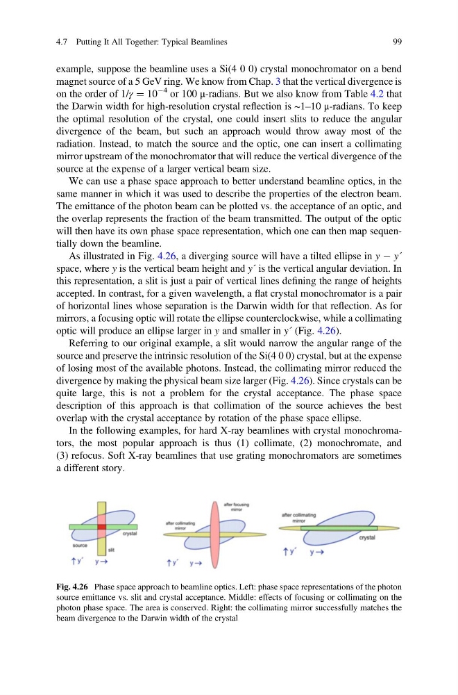
As illustrated in Fig. 4.26, a diverging source will have a tilted ellipse in y À y´
space, where y is the vertical beam height and y´ is the vertical angular deviation. In
this representation, a slit is just a pair of vertical lines defining the range of heights
accepted. In contrast, for a given wavelength, a flat crystal monochromator is a pair
of horizontal lines whose separation is the Darwin width for that reflection. As for
mirrors, a focusing optic will rotate the ellipse counterclockwise, while a collimating
optic will produce an ellipse larger in y and smaller in y´ (Fig. 4.26).
Referring to our original example, a slit would narrow the angular range of the
source and preserve the intrinsic resolution of the Si(4 0 0) crystal, but at the expense
of losing most of the available photons. Instead, the collimating mirror reduced the
divergence by making the physical beam size larger (Fig. 4.26). Since crystals can be
quite large, this is not a problem for the crystal acceptance. The phase space
description of this approach is that collimation of the source achieves the best
overlap with the crystal acceptance by rotation of the phase space ellipse.
In the following examples, for hard X-ray beamlines with crystal monochromators, the most popular approach is thus (1) collimate, (2) monochromate, and
(3) refocus. Soft X-ray beamlines that use grating monochromators are sometimes
a different story.
Fig. 4.26 Phase space approach to beamline optics. Left: phase space representations of the photon
source emittance vs. slit and crystal acceptance. Middle: effects of focusing or collimating on the
photon phase space. The area is conserved. Right: the collimating mirror successfully matches the
beam divergence to the Darwin width of the crystal
4.7 Putting It All Together: Typical Beamlines
99
magnet source of a 5 GeV ring. We know from Chap. 3 that the vertical divergence is
on the order of 1/γ ¼ 10
À4 or 100 μ-radians. But we also know from Table 4.2 that
the Darwin width for high-resolution crystal reflection is ~1–10 μ-radians. To keep
the optimal resolution of the crystal, one could insert slits to reduce the angular
divergence of the beam, but such an approach would throw away most of the
radiation. Instead, to match the source and the optic, one can insert a collimating
mirror upstream of the monochromator that will reduce the vertical divergence of the
source at the expense of a larger vertical beam size.
We can use a phase space approach to better understand beamline optics, in the
same manner in which it was used to describe the properties of the electron beam.
The emittance of the photon beam can be plotted vs. the acceptance of an optic, and
the overlap represents the fraction of the beam transmitted. The output of the optic
will then have its own phase space representation, which one can then map sequentially down the beamline.
As illustrated in Fig. 4.26, a diverging source will have a tilted ellipse in y À y´
space, where y is the vertical beam height and y´ is the vertical angular deviation. In
this representation, a slit is just a pair of vertical lines defining the range of heights
accepted. In contrast, for a given wavelength, a flat crystal monochromator is a pair
of horizontal lines whose separation is the Darwin width for that reflection. As for
mirrors, a focusing optic will rotate the ellipse counterclockwise, while a collimating
optic will produce an ellipse larger in y and smaller in y´ (Fig. 4.26).
Referring to our original example, a slit would narrow the angular range of the
source and preserve the intrinsic resolution of the Si(4 0 0) crystal, but at the expense
of losing most of the available photons. Instead, the collimating mirror reduced the
divergence by making the physical beam size larger (Fig. 4.26). Since crystals can be
quite large, this is not a problem for the crystal acceptance. The phase space
description of this approach is that collimation of the source achieves the best
overlap with the crystal acceptance by rotation of the phase space ellipse.
In the following examples, for hard X-ray beamlines with crystal monochromators, the most popular approach is thus (1) collimate, (2) monochromate, and
(3) refocus. Soft X-ray beamlines that use grating monochromators are sometimes
a different story.
Fig. 4.26 Phase space approach to beamline optics. Left: phase space representations of the photon
source emittance vs. slit and crystal acceptance. Middle: effects of focusing or collimating on the
photon phase space. The area is conserved. Right: the collimating mirror successfully matches the
beam divergence to the Darwin width of the crystal
4.7 Putting It All Together: Typical Beamlines
99