

4.6.5.1 Graded Multilayers
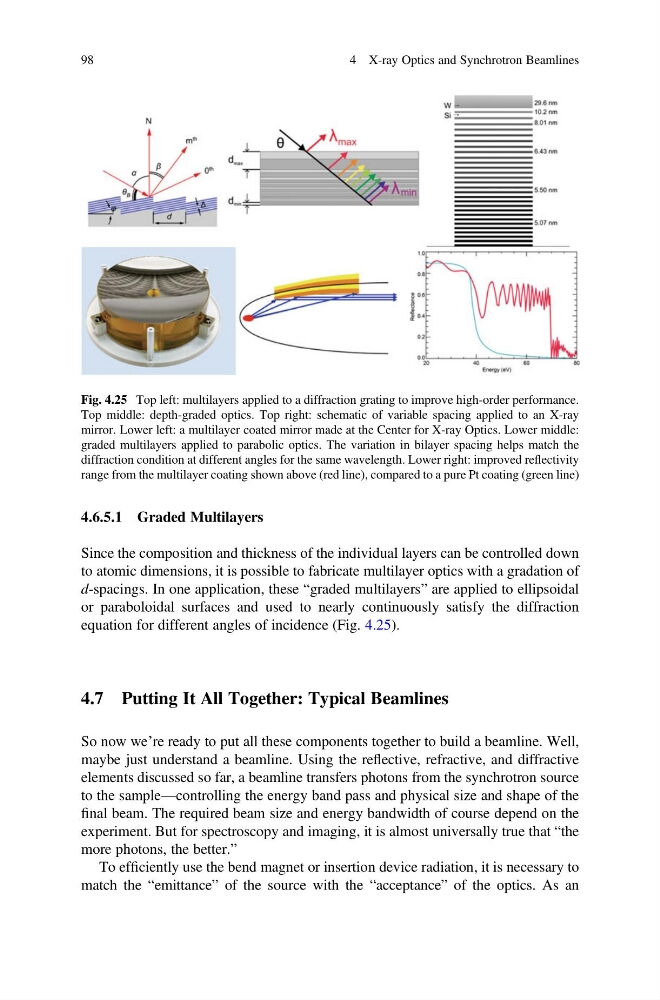
Since the composition and thickness of the individual layers can be controlled down
to atomic dimensions, it is possible to fabricate multilayer optics with a gradation of
d-spacings. In one application, these “graded multilayers” are applied to ellipsoidal
or paraboloidal surfaces and used to nearly continuously satisfy the diffraction
equation for different angles of incidence (Fig. 4.25).
4.7 Putting It All Together: Typical Beamlines
So now we’re ready to put all these components together to build a beamline. Well,
maybe just understand a beamline. Using the reflective, refractive, and diffractive
elements discussed so far, a beamline transfers photons from the synchrotron source
to the sample—controlling the energy band pass and physical size and shape of the
final beam. The required beam size and energy bandwidth of course depend on the
experiment. But for spectroscopy and imaging, it is almost universally true that “the
more photons, the better.”
To efficiently use the bend magnet or insertion device radiation, it is necessary to
match the “emittance” of the source with the “acceptance” of the optics. As an
Fig. 4.25 Top left: multilayers applied to a diffraction grating to improve high-order performance.
Top middle: depth-graded optics. Top right: schematic of variable spacing applied to an X-ray
mirror. Lower left: a multilayer coated mirror made at the Center for X-ray Optics. Lower middle:
graded multilayers applied to parabolic optics. The variation in bilayer spacing helps match the
diffraction condition at different angles for the same wavelength. Lower right: improved reflectivity
range from the multilayer coating shown above (red line), compared to a pure Pt coating (green line)
98
4 X-ray Optics and Synchrotron Beamlines
Since the composition and thickness of the individual layers can be controlled down
to atomic dimensions, it is possible to fabricate multilayer optics with a gradation of
d-spacings. In one application, these “graded multilayers” are applied to ellipsoidal
or paraboloidal surfaces and used to nearly continuously satisfy the diffraction
equation for different angles of incidence (Fig. 4.25).
4.7 Putting It All Together: Typical Beamlines
So now we’re ready to put all these components together to build a beamline. Well,
maybe just understand a beamline. Using the reflective, refractive, and diffractive
elements discussed so far, a beamline transfers photons from the synchrotron source
to the sample—controlling the energy band pass and physical size and shape of the
final beam. The required beam size and energy bandwidth of course depend on the
experiment. But for spectroscopy and imaging, it is almost universally true that “the
more photons, the better.”
To efficiently use the bend magnet or insertion device radiation, it is necessary to
match the “emittance” of the source with the “acceptance” of the optics. As an
Fig. 4.25 Top left: multilayers applied to a diffraction grating to improve high-order performance.
Top middle: depth-graded optics. Top right: schematic of variable spacing applied to an X-ray
mirror. Lower left: a multilayer coated mirror made at the Center for X-ray Optics. Lower middle:
graded multilayers applied to parabolic optics. The variation in bilayer spacing helps match the
diffraction condition at different angles for the same wavelength. Lower right: improved reflectivity
range from the multilayer coating shown above (red line), compared to a pure Pt coating (green line)
98
4 X-ray Optics and Synchrotron Beamlines