

The change in beam size is accompanied by a change in the angular ranges for
input and output. If ω S is the intrinsic Darwin width of the reflection in the
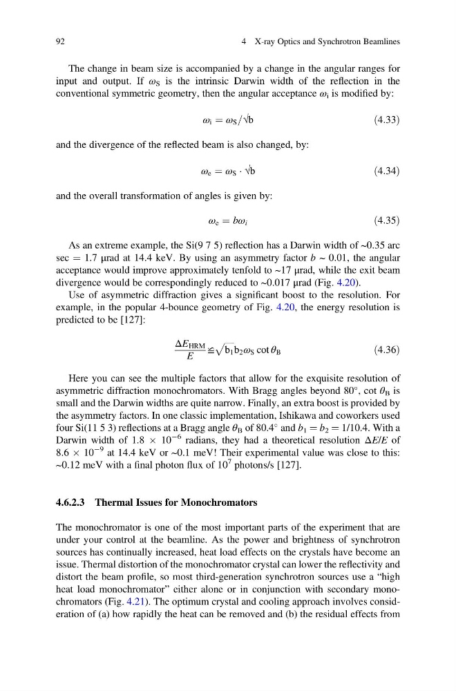
conventional symmetric geometry, then the angular acceptance ω i is modified by:
ω i ¼ ω S =√b
ð4:33Þ
and the divergence of the reflected beam is also changed, by:
ω e ¼ ω S Á √b
ð4:34Þ
and the overall transformation of angles is given by:
ω e ¼ bω i
ð4:35Þ
As an extreme example, the Si(9 7 5) reflection has a Darwin width of ~0.35 arc
sec ¼ 1.7 μrad at 14.4 keV. By using an asymmetry factor b ~ 0.01, the angular
acceptance would improve approximately tenfold to ~17 μrad, while the exit beam
divergence would be correspondingly reduced to ~0.017 μrad (Fig. 4.20).
Use of asymmetric diffraction gives a significant boost to the resolution. For
example, in the popular 4-bounce geometry of Fig. 4.20, the energy resolution is
predicted to be [127]:
ΔE HRM
E
≌
ffiffiffiffi ffi
b 1
p b 2 ω S cot θ B
ð4:36Þ
Here you can see the multiple factors that allow for the exquisite resolution of
asymmetric diffraction monochromators. With Bragg angles beyond 80
, cot θ B is
small and the Darwin widths are quite narrow. Finally, an extra boost is provided by
the asymmetry factors. In one classic implementation, Ishikawa and coworkers used
four Si(11 5 3) reflections at a Bragg angle θ B of 80.4
and b 1 ¼ b 2 ¼ 1/10.4. With a
Darwin width of 1.8 Â 10
À6 radians, they had a theoretical resolution ΔE/E of
8.6 Â 10
À9 at 14.4 keV or ~0.1 meV! Their experimental value was close to this:
~0.12 meV with a final photon flux of 10
7 photons/s [127].
4.6.2.3 Thermal Issues for Monochromators
The monochromator is one of the most important parts of the experiment that are
under your control at the beamline. As the power and brightness of synchrotron
sources has continually increased, heat load effects on the crystals have become an
issue. Thermal distortion of the monochromator crystal can lower the reflectivity and
distort the beam profile, so most third-generation synchrotron sources use a “high
heat load monochromator” either alone or in conjunction with secondary monochromators (Fig. 4.21). The optimum crystal and cooling approach involves consideration of (a) how rapidly the heat can be removed and (b) the residual effects from
92
4 X-ray Optics and Synchrotron Beamlines
input and output. If ω S is the intrinsic Darwin width of the reflection in the
conventional symmetric geometry, then the angular acceptance ω i is modified by:
ω i ¼ ω S =√b
ð4:33Þ
and the divergence of the reflected beam is also changed, by:
ω e ¼ ω S Á √b
ð4:34Þ
and the overall transformation of angles is given by:
ω e ¼ bω i
ð4:35Þ
As an extreme example, the Si(9 7 5) reflection has a Darwin width of ~0.35 arc
sec ¼ 1.7 μrad at 14.4 keV. By using an asymmetry factor b ~ 0.01, the angular
acceptance would improve approximately tenfold to ~17 μrad, while the exit beam
divergence would be correspondingly reduced to ~0.017 μrad (Fig. 4.20).
Use of asymmetric diffraction gives a significant boost to the resolution. For
example, in the popular 4-bounce geometry of Fig. 4.20, the energy resolution is
predicted to be [127]:
ΔE HRM
E
≌
ffiffiffiffi ffi
b 1
p b 2 ω S cot θ B
ð4:36Þ
Here you can see the multiple factors that allow for the exquisite resolution of
asymmetric diffraction monochromators. With Bragg angles beyond 80
, cot θ B is
small and the Darwin widths are quite narrow. Finally, an extra boost is provided by
the asymmetry factors. In one classic implementation, Ishikawa and coworkers used
four Si(11 5 3) reflections at a Bragg angle θ B of 80.4
and b 1 ¼ b 2 ¼ 1/10.4. With a
Darwin width of 1.8 Â 10
À6 radians, they had a theoretical resolution ΔE/E of
8.6 Â 10
À9 at 14.4 keV or ~0.1 meV! Their experimental value was close to this:
~0.12 meV with a final photon flux of 10
7 photons/s [127].
4.6.2.3 Thermal Issues for Monochromators
The monochromator is one of the most important parts of the experiment that are
under your control at the beamline. As the power and brightness of synchrotron
sources has continually increased, heat load effects on the crystals have become an
issue. Thermal distortion of the monochromator crystal can lower the reflectivity and
distort the beam profile, so most third-generation synchrotron sources use a “high
heat load monochromator” either alone or in conjunction with secondary monochromators (Fig. 4.21). The optimum crystal and cooling approach involves consideration of (a) how rapidly the heat can be removed and (b) the residual effects from
92
4 X-ray Optics and Synchrotron Beamlines