

investigator. Thus, there are many investigators who are using the information in
DNA to form nanoscale materials and structures for a variety of purposes. The
growth of this field in the last decade is arguably the most important thing that has
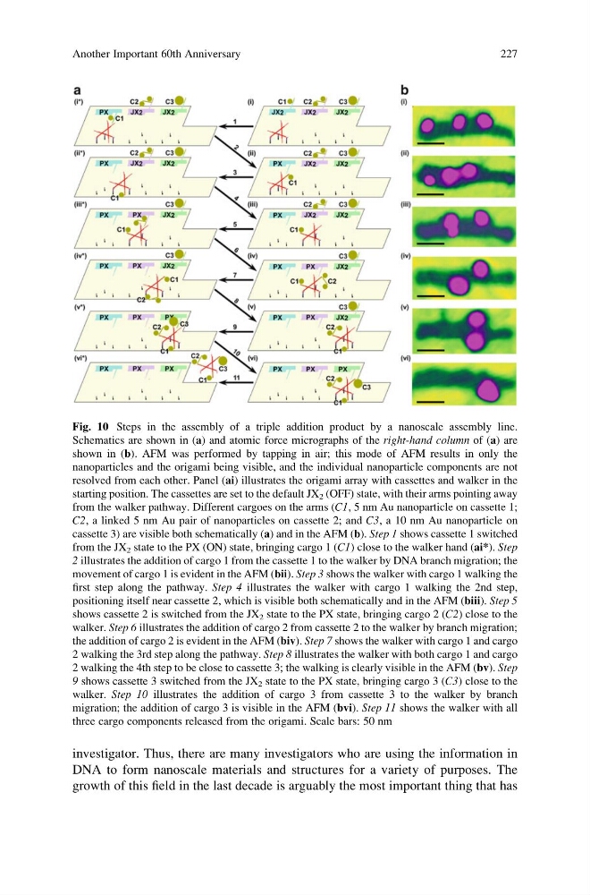
Fig. 10 Steps in the assembly of a triple addition product by a nanoscale assembly line.
Schematics are shown in (a) and atomic force micrographs of the right-hand column of (a) are
shown in (b). AFM was performed by tapping in air; this mode of AFM results in only the
nanoparticles and the origami being visible, and the individual nanoparticle components are not
resolved from each other. Panel (ai) illustrates the origami array with cassettes and walker in the
starting position. The cassettes are set to the default JX 2 (OFF) state, with their arms pointing away
from the walker pathway. Different cargoes on the arms (C1, 5 nm Au nanoparticle on cassette 1;
C2, a linked 5 nm Au pair of nanoparticles on cassette 2; and C3, a 10 nm Au nanoparticle on
cassette 3) are visible both schematically (a) and in the AFM (b). Step 1 shows cassette 1 switched
from the JX 2 state to the PX (ON) state, bringing cargo 1 (C1) close to the walker hand (ai*). Step
2 illustrates the addition of cargo 1 from the cassette 1 to the walker by DNA branch migration; the
movement of cargo 1 is evident in the AFM (bii). Step 3 shows the walker with cargo 1 walking the
first step along the pathway. Step 4 illustrates the walker with cargo 1 walking the 2nd step,
positioning itself near cassette 2, which is visible both schematically and in the AFM (biii). Step 5
shows cassette 2 is switched from the JX 2 state to the PX state, bringing cargo 2 (C2) close to the
walker. Step 6 illustrates the addition of cargo 2 from cassette 2 to the walker by branch migration;
the addition of cargo 2 is evident in the AFM (biv). Step 7 shows the walker with cargo 1 and cargo
2 walking the 3rd step along the pathway. Step 8 illustrates the walker with both cargo 1 and cargo
2 walking the 4th step to be close to cassette 3; the walking is clearly visible in the AFM (bv). Step
9 shows cassette 3 switched from the JX 2 state to the PX state, bringing cargo 3 (C3) close to the
walker. Step 10 illustrates the addition of cargo 3 from cassette 3 to the walker by branch
migration; the addition of cargo 3 is visible in the AFM (bvi). Step 11 shows the walker with all
three cargo components released from the origami. Scale bars: 50 nm
Another Important 60th Anniversary
227
DNA to form nanoscale materials and structures for a variety of purposes. The
growth of this field in the last decade is arguably the most important thing that has
Fig. 10 Steps in the assembly of a triple addition product by a nanoscale assembly line.
Schematics are shown in (a) and atomic force micrographs of the right-hand column of (a) are
shown in (b). AFM was performed by tapping in air; this mode of AFM results in only the
nanoparticles and the origami being visible, and the individual nanoparticle components are not
resolved from each other. Panel (ai) illustrates the origami array with cassettes and walker in the
starting position. The cassettes are set to the default JX 2 (OFF) state, with their arms pointing away
from the walker pathway. Different cargoes on the arms (C1, 5 nm Au nanoparticle on cassette 1;
C2, a linked 5 nm Au pair of nanoparticles on cassette 2; and C3, a 10 nm Au nanoparticle on
cassette 3) are visible both schematically (a) and in the AFM (b). Step 1 shows cassette 1 switched
from the JX 2 state to the PX (ON) state, bringing cargo 1 (C1) close to the walker hand (ai*). Step
2 illustrates the addition of cargo 1 from the cassette 1 to the walker by DNA branch migration; the
movement of cargo 1 is evident in the AFM (bii). Step 3 shows the walker with cargo 1 walking the
first step along the pathway. Step 4 illustrates the walker with cargo 1 walking the 2nd step,
positioning itself near cassette 2, which is visible both schematically and in the AFM (biii). Step 5
shows cassette 2 is switched from the JX 2 state to the PX state, bringing cargo 2 (C2) close to the
walker. Step 6 illustrates the addition of cargo 2 from cassette 2 to the walker by branch migration;
the addition of cargo 2 is evident in the AFM (biv). Step 7 shows the walker with cargo 1 and cargo
2 walking the 3rd step along the pathway. Step 8 illustrates the walker with both cargo 1 and cargo
2 walking the 4th step to be close to cassette 3; the walking is clearly visible in the AFM (bv). Step
9 shows cassette 3 switched from the JX 2 state to the PX state, bringing cargo 3 (C3) close to the
walker. Step 10 illustrates the addition of cargo 3 from cassette 3 to the walker by branch
migration; the addition of cargo 3 is visible in the AFM (bvi). Step 11 shows the walker with all
three cargo components released from the origami. Scale bars: 50 nm
Another Important 60th Anniversary
227