

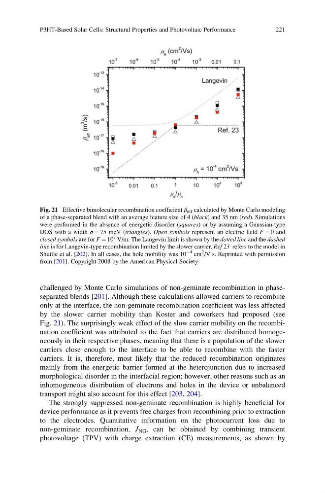
challenged by Monte Carlo simulations of non-geminate recombination in phaseseparated blends [201]. Although these calculations allowed carriers to recombine
only at the interface, the non-geminate recombination coefficient was less affected
by the slower carrier mobility than Koster and coworkers had proposed (see
Fig. 21). The surprisingly weak effect of the slow carrier mobility on the recombination coefficient was attributed to the fact that carriers are distributed homogeneously in their respective phases, meaning that there is a population of the slower
carriers close enough to the interface to be able to recombine with the faster
carriers. It is, therefore, most likely that the reduced recombination originates
mainly from the energetic barrier formed at the heterojunction due to increased
morphological disorder in the interfacial region; however, other reasons such as an
inhomogeneous distribution of electrons and holes in the device or unbalanced
transport might also account for this effect [203, 204].
The strongly suppressed non-geminate recombination is highly beneficial for
device performance as it prevents free charges from recombining prior to extraction
to the electrodes. Quantitative information on the photocurrent loss due to
non-geminate recombination, J NG , can be obtained by combining transient
photovoltage (TPV) with charge extraction (CE) measurements, as shown by
Fig. 21 Effective bimolecular recombination coefficient β eff calculated by Monte Carlo modeling
of a phase-separated blend with an average feature size of 4 (black) and 35 nm (red). Simulations
were performed in the absence of energetic disorder (squares) or by assuming a Gaussian-type
DOS with a width σ ¼ 75 meV (triangles). Open symbols represent an electric field F ¼ 0 and
closed symbols are for F ¼ 10
7 V/m. The Langevin limit is shown by the dotted line and the dashed
line is for Langevin-type recombination limited by the slower carrier. Ref 23 refers to the model in
Shuttle et al. [202]. In all cases, the hole mobility was 10
À4 cm
2
/V s. Reprinted with permission
from [201]. Copyright 2008 by the American Physical Society
P3HT-Based Solar Cells: Structural Properties and Photovoltaic Performance
221
only at the interface, the non-geminate recombination coefficient was less affected
by the slower carrier mobility than Koster and coworkers had proposed (see
Fig. 21). The surprisingly weak effect of the slow carrier mobility on the recombination coefficient was attributed to the fact that carriers are distributed homogeneously in their respective phases, meaning that there is a population of the slower
carriers close enough to the interface to be able to recombine with the faster
carriers. It is, therefore, most likely that the reduced recombination originates
mainly from the energetic barrier formed at the heterojunction due to increased
morphological disorder in the interfacial region; however, other reasons such as an
inhomogeneous distribution of electrons and holes in the device or unbalanced
transport might also account for this effect [203, 204].
The strongly suppressed non-geminate recombination is highly beneficial for
device performance as it prevents free charges from recombining prior to extraction
to the electrodes. Quantitative information on the photocurrent loss due to
non-geminate recombination, J NG , can be obtained by combining transient
photovoltage (TPV) with charge extraction (CE) measurements, as shown by
Fig. 21 Effective bimolecular recombination coefficient β eff calculated by Monte Carlo modeling
of a phase-separated blend with an average feature size of 4 (black) and 35 nm (red). Simulations
were performed in the absence of energetic disorder (squares) or by assuming a Gaussian-type
DOS with a width σ ¼ 75 meV (triangles). Open symbols represent an electric field F ¼ 0 and
closed symbols are for F ¼ 10
7 V/m. The Langevin limit is shown by the dotted line and the dashed
line is for Langevin-type recombination limited by the slower carrier. Ref 23 refers to the model in
Shuttle et al. [202]. In all cases, the hole mobility was 10
À4 cm
2
/V s. Reprinted with permission
from [201]. Copyright 2008 by the American Physical Society
P3HT-Based Solar Cells: Structural Properties and Photovoltaic Performance
221