

composite can be confirmed from the prominent peaks corresponding to the
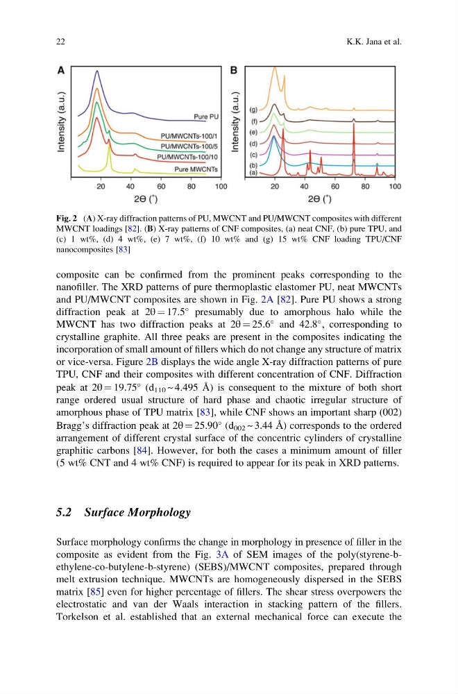
nanofiller. The XRD patterns of pure thermoplastic elastomer PU, neat MWCNTs
and PU/MWCNT composites are shown in Fig. 2A [82]. Pure PU shows a strong
diffraction peak at 2θ ¼ 17.5
presumably due to amorphous halo while the
MWCNT has two diffraction peaks at 2θ ¼ 25.6
and 42.8
, corresponding to
crystalline graphite. All three peaks are present in the composites indicating the
incorporation of small amount of fillers which do not change any structure of matrix
or vice-versa. Figure 2B displays the wide angle X-ray diffraction patterns of pure
TPU, CNF and their composites with different concentration of CNF. Diffraction
peak at 2θ ¼ 19.75
(d 110 ~ 4.495 Å) is consequent to the mixture of both short
range ordered usual structure of hard phase and chaotic irregular structure of
amorphous phase of TPU matrix [83], while CNF shows an important sharp (002)
Bragg’s diffraction peak at 2θ ¼ 25.90
(d 002 ~ 3.44 Å) corresponds to the ordered
arrangement of different crystal surface of the concentric cylinders of crystalline
graphitic carbons [84]. However, for both the cases a minimum amount of filler
(5 wt% CNT and 4 wt% CNF) is required to appear for its peak in XRD patterns.
5.2 Surface Morphology
Surface morphology confirms the change in morphology in presence of filler in the
composite as evident from the Fig. 3A of SEM images of the poly(styrene-bethylene-co-butylene-b-styrene) (SEBS)/MWCNT composites, prepared through
melt extrusion technique. MWCNTs are homogeneously dispersed in the SEBS
matrix [85] even for higher percentage of fillers. The shear stress overpowers the
electrostatic and van der Waals interaction in stacking pattern of the fillers.
Torkelson et al. established that an external mechanical force can execute the
Fig. 2 (A) X-ray diffraction patterns of PU, MWCNT and PU/MWCNT composites with different
MWCNT loadings [82]. (B) X-ray patterns of CNF composites, (a) neat CNF, (b) pure TPU, and
(c) 1 wt%, (d) 4 wt%, (e) 7 wt%, (f) 10 wt% and (g) 15 wt% CNF loading TPU/CNF
nanocomposites [83]
22
K.K. Jana et al.
nanofiller. The XRD patterns of pure thermoplastic elastomer PU, neat MWCNTs
and PU/MWCNT composites are shown in Fig. 2A [82]. Pure PU shows a strong
diffraction peak at 2θ ¼ 17.5
presumably due to amorphous halo while the
MWCNT has two diffraction peaks at 2θ ¼ 25.6
and 42.8
, corresponding to
crystalline graphite. All three peaks are present in the composites indicating the
incorporation of small amount of fillers which do not change any structure of matrix
or vice-versa. Figure 2B displays the wide angle X-ray diffraction patterns of pure
TPU, CNF and their composites with different concentration of CNF. Diffraction
peak at 2θ ¼ 19.75
(d 110 ~ 4.495 Å) is consequent to the mixture of both short
range ordered usual structure of hard phase and chaotic irregular structure of
amorphous phase of TPU matrix [83], while CNF shows an important sharp (002)
Bragg’s diffraction peak at 2θ ¼ 25.90
(d 002 ~ 3.44 Å) corresponds to the ordered
arrangement of different crystal surface of the concentric cylinders of crystalline
graphitic carbons [84]. However, for both the cases a minimum amount of filler
(5 wt% CNT and 4 wt% CNF) is required to appear for its peak in XRD patterns.
5.2 Surface Morphology
Surface morphology confirms the change in morphology in presence of filler in the
composite as evident from the Fig. 3A of SEM images of the poly(styrene-bethylene-co-butylene-b-styrene) (SEBS)/MWCNT composites, prepared through
melt extrusion technique. MWCNTs are homogeneously dispersed in the SEBS
matrix [85] even for higher percentage of fillers. The shear stress overpowers the
electrostatic and van der Waals interaction in stacking pattern of the fillers.
Torkelson et al. established that an external mechanical force can execute the
Fig. 2 (A) X-ray diffraction patterns of PU, MWCNT and PU/MWCNT composites with different
MWCNT loadings [82]. (B) X-ray patterns of CNF composites, (a) neat CNF, (b) pure TPU, and
(c) 1 wt%, (d) 4 wt%, (e) 7 wt%, (f) 10 wt% and (g) 15 wt% CNF loading TPU/CNF
nanocomposites [83]
22
K.K. Jana et al.