

46
3 Materials and Methods
Step 3
From Eq. 4.15 in Chap. 4,
pk X S w θ
(S 0 −S w )(K +S w )
+
a Jθ
(S 0 −S w )
= 1
{(X θ S w )/(S 0 −S w )(K +S w )}
1/ pk
+
θ/(S 0 −S w )
1/a J
= 1
Now,
X θ S w
(S 0 −S w )(K +S w )
values can be plotted with respect to
θ
(S 0 −S w )
and a best-fit
line can be drawn as shown in Fig. 4d, Annexure I-b.
Let 1/(pk) = intercept in Y-axis (m) and 1/aJ = intercept in X-axis (n), Hence, k
= 1/pm and J = 1/an.
Again, k = µm/Y ≥ Y = µm/k.
The maximum specific substrate utilization rate (k) can be determined from the
Y-intercept of Fig. 4d of Annexure I-b, provided the porosity of the hybrid bioreactor
in terms of attached phase is known. On the other hand, the ‘J’ value evaluated from
the X-intercept of Fig. 4d of Annexure I-b represents the mean substrate flux through
the attached biofilm in the hybrid bioreactor.
Step 4
Equation 4.14 in Chap. 4 yields the biomass balance for the suspended-growth system
as,
=>
Y a J avg
pX
b s
b s +b d
=
1
θ c
−
Y kS w
K +S w
+ b d
=>
Y a J avg
pX
=
1
θ c
−
Y kS w
K +S w
b s +b d
b s
+ b d
b s +b d
b s
Now,
Y a J
pX
values can be plotted with respect to
1
θ c
−
Y kS w
K +S w
values and a best-fit
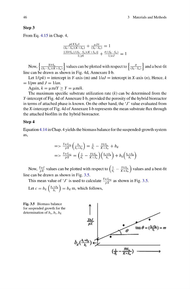
line can be drawn as shown in Fig. 3.5.
This mean value of ‘J’ is used to calculate
Y a J avg
pX
as shown in Fig. 3.5.
Let c = b d
b s +b d
b s
= b d m, which follows,
Fig. 3.5 Biomass balance
for suspended growth for the
determination of b s , b t , b d
3 Materials and Methods
Step 3
From Eq. 4.15 in Chap. 4,
pk X S w θ
(S 0 −S w )(K +S w )
+
a Jθ
(S 0 −S w )
= 1
{(X θ S w )/(S 0 −S w )(K +S w )}
1/ pk
+
θ/(S 0 −S w )
1/a J
= 1
Now,
X θ S w
(S 0 −S w )(K +S w )
values can be plotted with respect to
θ
(S 0 −S w )
and a best-fit
line can be drawn as shown in Fig. 4d, Annexure I-b.
Let 1/(pk) = intercept in Y-axis (m) and 1/aJ = intercept in X-axis (n), Hence, k
= 1/pm and J = 1/an.
Again, k = µm/Y ≥ Y = µm/k.
The maximum specific substrate utilization rate (k) can be determined from the
Y-intercept of Fig. 4d of Annexure I-b, provided the porosity of the hybrid bioreactor
in terms of attached phase is known. On the other hand, the ‘J’ value evaluated from
the X-intercept of Fig. 4d of Annexure I-b represents the mean substrate flux through
the attached biofilm in the hybrid bioreactor.
Step 4
Equation 4.14 in Chap. 4 yields the biomass balance for the suspended-growth system
as,
=>
Y a J avg
pX
b s
b s +b d
=
1
θ c
−
Y kS w
K +S w
+ b d
=>
Y a J avg
pX
=
1
θ c
−
Y kS w
K +S w
b s +b d
b s
+ b d
b s +b d
b s
Now,
Y a J
pX
values can be plotted with respect to
1
θ c
−
Y kS w
K +S w
values and a best-fit
line can be drawn as shown in Fig. 3.5.
This mean value of ‘J’ is used to calculate
Y a J avg
pX
as shown in Fig. 3.5.
Let c = b d
b s +b d
b s
= b d m, which follows,
Fig. 3.5 Biomass balance
for suspended growth for the
determination of b s , b t , b d