

Recent Advances in the Analysis, Measurement, and Properties …
211
(a)
(d)
(e)
(b)
(c)
(f)
200 μm
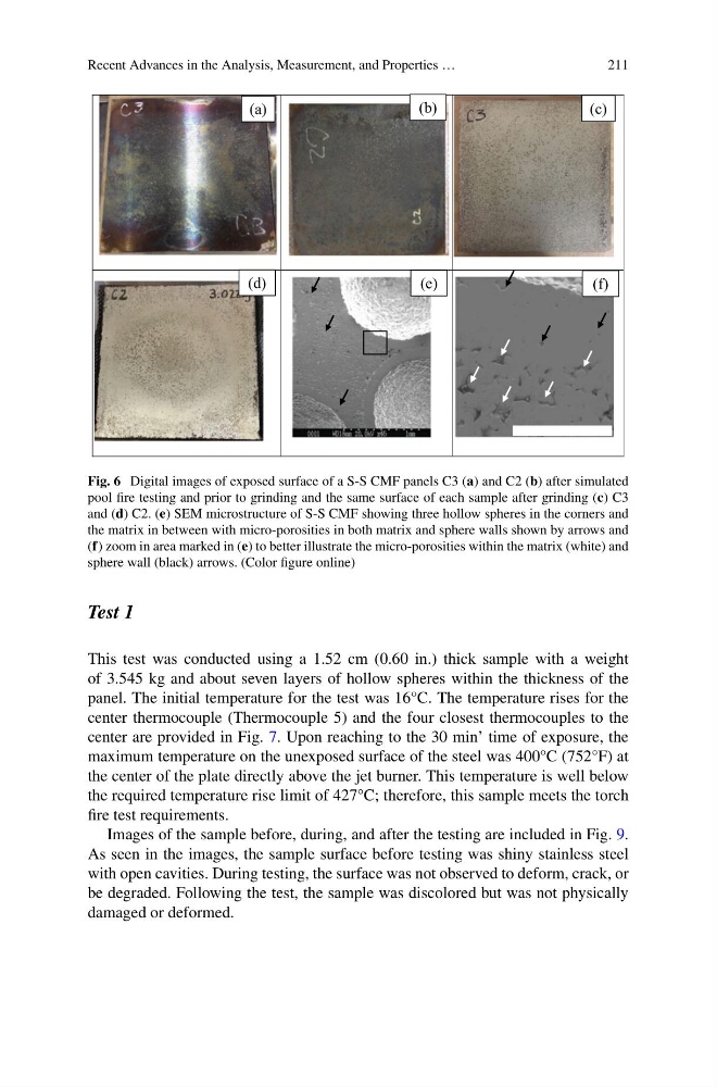
Fig. 6 Digital images of exposed surface of a S-S CMF panels C3 (a) and C2 (b) after simulated
pool fire testing and prior to grinding and the same surface of each sample after grinding (c) C3
and (d) C2. (e) SEM microstructure of S-S CMF showing three hollow spheres in the corners and
the matrix in between with micro-porosities in both matrix and sphere walls shown by arrows and
(f) zoom in area marked in (e) to better illustrate the micro-porosities within the matrix (white) and
sphere wall (black) arrows. (Color figure online)
Test 1
This test was conducted using a 1.52 cm (0.60 in.) thick sample with a weight
of 3.545 kg and about seven layers of hollow spheres within the thickness of the
panel. The initial temperature for the test was 16°C. The temperature rises for the
center thermocouple (Thermocouple 5) and the four closest thermocouples to the
center are provided in Fig. 7. Upon reaching to the 30 min’ time of exposure, the
maximum temperature on the unexposed surface of the steel was 400°C (752°F) at
the center of the plate directly above the jet burner. This temperature is well below
the required temperature rise limit of 427°C; therefore, this sample meets the torch
fire test requirements.
Images of the sample before, during, and after the testing are included in Fig. 9.
As seen in the images, the sample surface before testing was shiny stainless steel
with open cavities. During testing, the surface was not observed to deform, crack, or
be degraded. Following the test, the sample was discolored but was not physically
damaged or deformed.
211
(a)
(d)
(e)
(b)
(c)
(f)
200 μm
Fig. 6 Digital images of exposed surface of a S-S CMF panels C3 (a) and C2 (b) after simulated
pool fire testing and prior to grinding and the same surface of each sample after grinding (c) C3
and (d) C2. (e) SEM microstructure of S-S CMF showing three hollow spheres in the corners and
the matrix in between with micro-porosities in both matrix and sphere walls shown by arrows and
(f) zoom in area marked in (e) to better illustrate the micro-porosities within the matrix (white) and
sphere wall (black) arrows. (Color figure online)
Test 1
This test was conducted using a 1.52 cm (0.60 in.) thick sample with a weight
of 3.545 kg and about seven layers of hollow spheres within the thickness of the
panel. The initial temperature for the test was 16°C. The temperature rises for the
center thermocouple (Thermocouple 5) and the four closest thermocouples to the
center are provided in Fig. 7. Upon reaching to the 30 min’ time of exposure, the
maximum temperature on the unexposed surface of the steel was 400°C (752°F) at
the center of the plate directly above the jet burner. This temperature is well below
the required temperature rise limit of 427°C; therefore, this sample meets the torch
fire test requirements.
Images of the sample before, during, and after the testing are included in Fig. 9.
As seen in the images, the sample surface before testing was shiny stainless steel
with open cavities. During testing, the surface was not observed to deform, crack, or
be degraded. Following the test, the sample was discolored but was not physically
damaged or deformed.