

154
T. Das
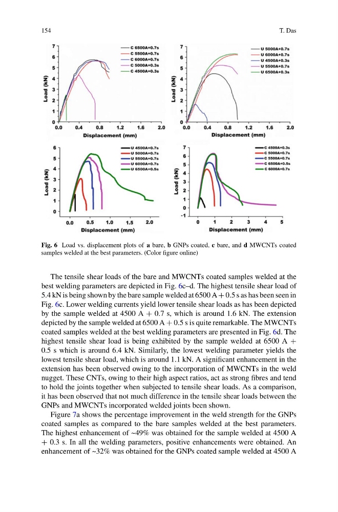
Fig. 6 Load vs. displacement plots of a bare, b GNPs coated, c bare, and d MWCNTs coated
samples welded at the best parameters. (Color figure online)
The tensile shear loads of the bare and MWCNTs coated samples welded at the
best welding parameters are depicted in Fig. 6c–d. The highest tensile shear load of
5.4 kN is being shown by the bare sample welded at 6500 A + 0.5 s as has been seen in
Fig. 6c. Lower welding currents yield lower tensile shear loads as has been depicted
by the sample welded at 4500 A + 0.7 s, which is around 1.6 kN. The extension
depicted by the sample welded at 6500 A + 0.5 s is quite remarkable. The MWCNTs
coated samples welded at the best welding parameters are presented in Fig. 6d. The
highest tensile shear load is being exhibited by the sample welded at 6500 A +
0.5 s which is around 6.4 kN. Similarly, the lowest welding parameter yields the
lowest tensile shear load, which is around 1.1 kN. A significant enhancement in the
extension has been observed owing to the incorporation of MWCNTs in the weld
nugget. These CNTs, owing to their high aspect ratios, act as strong fibres and tend
to hold the joints together when subjected to tensile shear loads. As a comparison,
it has been observed that not much difference in the tensile shear loads between the
GNPs and MWCNTs incorporated welded joints been shown.
Figure 7a shows the percentage improvement in the weld strength for the GNPs
coated samples as compared to the bare samples welded at the best parameters.
The highest enhancement of ~49% was obtained for the sample welded at 4500 A
+ 0.3 s. In all the welding parameters, positive enhancements were obtained. An
enhancement of ~32% was obtained for the GNPs coated sample welded at 4500 A
T. Das
Fig. 6 Load vs. displacement plots of a bare, b GNPs coated, c bare, and d MWCNTs coated
samples welded at the best parameters. (Color figure online)
The tensile shear loads of the bare and MWCNTs coated samples welded at the
best welding parameters are depicted in Fig. 6c–d. The highest tensile shear load of
5.4 kN is being shown by the bare sample welded at 6500 A + 0.5 s as has been seen in
Fig. 6c. Lower welding currents yield lower tensile shear loads as has been depicted
by the sample welded at 4500 A + 0.7 s, which is around 1.6 kN. The extension
depicted by the sample welded at 6500 A + 0.5 s is quite remarkable. The MWCNTs
coated samples welded at the best welding parameters are presented in Fig. 6d. The
highest tensile shear load is being exhibited by the sample welded at 6500 A +
0.5 s which is around 6.4 kN. Similarly, the lowest welding parameter yields the
lowest tensile shear load, which is around 1.1 kN. A significant enhancement in the
extension has been observed owing to the incorporation of MWCNTs in the weld
nugget. These CNTs, owing to their high aspect ratios, act as strong fibres and tend
to hold the joints together when subjected to tensile shear loads. As a comparison,
it has been observed that not much difference in the tensile shear loads between the
GNPs and MWCNTs incorporated welded joints been shown.
Figure 7a shows the percentage improvement in the weld strength for the GNPs
coated samples as compared to the bare samples welded at the best parameters.
The highest enhancement of ~49% was obtained for the sample welded at 4500 A
+ 0.3 s. In all the welding parameters, positive enhancements were obtained. An
enhancement of ~32% was obtained for the GNPs coated sample welded at 4500 A