

SP300 ¼ 2,073,079 CV) were used. In addition, a boundary layer along the vessel
walls was implemented to improve the resolution of effects close to the vessel walls.
The CFD simulations were performed using the ANSYS Fluent finite volume solver.
The implemented pressure-based solver, with an absolute velocity formulation, was
used for all simulations. The walls were treated as non-slip boundaries with standard
wall functions. The liquid surfaces were treated as symmetry planes, with the fluid
velocities normal to the face set to zero. The MCs were implemented in the
simulations using (I) a Euler-Euler granular model or (II) a Euler-Lagrange
approach with discrete particle modelling and tracking. In general, water (ρ L ¼
993 kg/m
3 , η L ¼ 0.6913 mPa s at 37
C) and the MC beads (d p,mean ¼ 169 μm, ρ p ¼
1,026 kg/m
3 ) were considered in the models. The initialization of the MCs was
carried out either with settled beads (directly at the reactor bottom α MC up to 0.63) or
with beads that were homogenously distributed over the entire fluid domain. SIMPLE (semi-implicit method for pressure-linked equations) and phase-coupled SIMPLE algorithms were used for pressure-velocity coupling in the single- and multiphase models. All simulations were run in parallel and solved on a computational
cluster (up to 16 Intel Xeno
® E5-2630 v4 CPU’s @ 2.2 GHz, 64 GB RAM).
3.2.2 Results from Single-Phase Modelling
As shown in Fig. 5a, b, the steady-state fluid flow profiles in the two spinner flask
types were similar due to their comparable geometrical ratios. In both cases, the
highest fluid velocities occurred at the edges of the impeller blades and in the
impeller wake. The maximum fluid velocities were slightly higher ( 5%) than the
theoretical u tip , which could mainly be attributed to numerical uncertainties. However, the observations are in agreement with literature data for disk stirrers. For
example, Stoots et al. [90] and Wollny [91] demonstrated that the peak tangential
velocities in the impeller wake can be up to % 1.4 (experimental) and % 1.5
(numeric) times higher than the impeller speed. An area with relatively weak fluid
velocities (u/u tip < 0.1) was generated directly below the impeller (r/R Æ 0.3) in both
systems. Thus, this area represented a critical zone for MC sedimentation. The
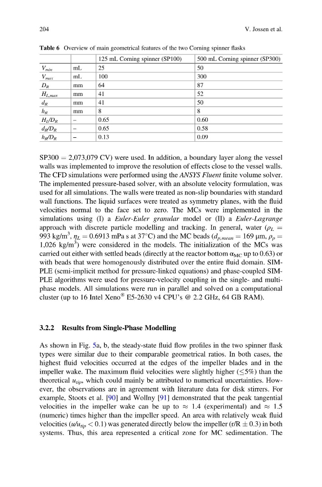
Table 6 Overview of main geometrical features of the two Corning spinner flasks
125 mL Corning spinner (SP100)
500 mL Corning spinner (SP300)
V min
mL
25
50
V max
mL
100
300
D R
mm
64
87
H L,max
mm
41
52
d R
mm
41
50
h R
mm
8
8
H L /D R
–
0.65
0.60
d R /D R
–
0.65
0.58
h R /D R
–
0.13
0.09
204
V. Jossen et al.
walls was implemented to improve the resolution of effects close to the vessel walls.
The CFD simulations were performed using the ANSYS Fluent finite volume solver.
The implemented pressure-based solver, with an absolute velocity formulation, was
used for all simulations. The walls were treated as non-slip boundaries with standard
wall functions. The liquid surfaces were treated as symmetry planes, with the fluid
velocities normal to the face set to zero. The MCs were implemented in the
simulations using (I) a Euler-Euler granular model or (II) a Euler-Lagrange
approach with discrete particle modelling and tracking. In general, water (ρ L ¼
993 kg/m
3 , η L ¼ 0.6913 mPa s at 37
C) and the MC beads (d p,mean ¼ 169 μm, ρ p ¼
1,026 kg/m
3 ) were considered in the models. The initialization of the MCs was
carried out either with settled beads (directly at the reactor bottom α MC up to 0.63) or
with beads that were homogenously distributed over the entire fluid domain. SIMPLE (semi-implicit method for pressure-linked equations) and phase-coupled SIMPLE algorithms were used for pressure-velocity coupling in the single- and multiphase models. All simulations were run in parallel and solved on a computational
cluster (up to 16 Intel Xeno
® E5-2630 v4 CPU’s @ 2.2 GHz, 64 GB RAM).
3.2.2 Results from Single-Phase Modelling
As shown in Fig. 5a, b, the steady-state fluid flow profiles in the two spinner flask
types were similar due to their comparable geometrical ratios. In both cases, the
highest fluid velocities occurred at the edges of the impeller blades and in the
impeller wake. The maximum fluid velocities were slightly higher ( 5%) than the
theoretical u tip , which could mainly be attributed to numerical uncertainties. However, the observations are in agreement with literature data for disk stirrers. For
example, Stoots et al. [90] and Wollny [91] demonstrated that the peak tangential
velocities in the impeller wake can be up to % 1.4 (experimental) and % 1.5
(numeric) times higher than the impeller speed. An area with relatively weak fluid
velocities (u/u tip < 0.1) was generated directly below the impeller (r/R Æ 0.3) in both
systems. Thus, this area represented a critical zone for MC sedimentation. The
Table 6 Overview of main geometrical features of the two Corning spinner flasks
125 mL Corning spinner (SP100)
500 mL Corning spinner (SP300)
V min
mL
25
50
V max
mL
100
300
D R
mm
64
87
H L,max
mm
41
52
d R
mm
41
50
h R
mm
8
8
H L /D R
–
0.65
0.60
d R /D R
–
0.65
0.58
h R /D R
–
0.13
0.09
204
V. Jossen et al.