

6.5 Multi-tag 3D Position Measurement Based on Image Match
227
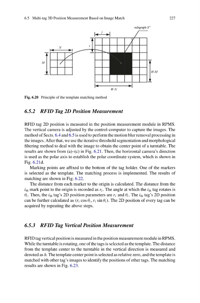
Fig. 6.20 Principle of the template matching method
6.5.2 RFID Tag 2D Position Measurement
RFID tag 2D position is measured in the position measurement module in RPMS.
The vertical camera is adjusted by the control-computer to capture the images. The
method of Sects. 6.4 and 6.5 is used to perform the motion blur removal processing in
the images. After that, we use the iterative threshold segmentation and morphological
filtering method to deal with the image to obtain the center point of a turntable. The
results are shown from (a)–(c) in Fig. 6.21. Then, the horizontal camera’s direction
is used as the polar axis to establish the polar coordinate system, which is shown in
Fig. 6.21d.
Marking points are affixed to the bottom of the tag holder. One of the markers
is selected as the template. The matching process is implemented. The results of
matching are shown in Fig. 6.22.
The distance from each marker to the origin is calculated. The distance from the
i th mark point to the origin is recorded as r i . The angle at which the i th tag rotates is
θ i . Then, the i th tag’s 2D position parameters are r i and θ i . The i th tag’s 2D position
can be further calculated as (r i cos θ i , r i sin θ i ). The 2D position of every tag can be
acquired by repeating the above steps.
6.5.3 RFID Tag Vertical Position Measurement
RFID tag vertical position is measured in the position measurement module in RPMS.
While the turntable is rotating, one of the tags is selected as the template. The distance
from the template center to the turntable in the vertical direction is measured and
denoted as h. The template center point is selected as relative zero, and the template is
matched with other tag’s images to identify the positions of other tags. The matching
results are shown in Fig. 6.23.
227
Fig. 6.20 Principle of the template matching method
6.5.2 RFID Tag 2D Position Measurement
RFID tag 2D position is measured in the position measurement module in RPMS.
The vertical camera is adjusted by the control-computer to capture the images. The
method of Sects. 6.4 and 6.5 is used to perform the motion blur removal processing in
the images. After that, we use the iterative threshold segmentation and morphological
filtering method to deal with the image to obtain the center point of a turntable. The
results are shown from (a)–(c) in Fig. 6.21. Then, the horizontal camera’s direction
is used as the polar axis to establish the polar coordinate system, which is shown in
Fig. 6.21d.
Marking points are affixed to the bottom of the tag holder. One of the markers
is selected as the template. The matching process is implemented. The results of
matching are shown in Fig. 6.22.
The distance from each marker to the origin is calculated. The distance from the
i th mark point to the origin is recorded as r i . The angle at which the i th tag rotates is
θ i . Then, the i th tag’s 2D position parameters are r i and θ i . The i th tag’s 2D position
can be further calculated as (r i cos θ i , r i sin θ i ). The 2D position of every tag can be
acquired by repeating the above steps.
6.5.3 RFID Tag Vertical Position Measurement
RFID tag vertical position is measured in the position measurement module in RPMS.
While the turntable is rotating, one of the tags is selected as the template. The distance
from the template center to the turntable in the vertical direction is measured and
denoted as h. The template center point is selected as relative zero, and the template is
matched with other tag’s images to identify the positions of other tags. The matching
results are shown in Fig. 6.23.