

64
3 Experimental Methods in Characterization of Nanosystems
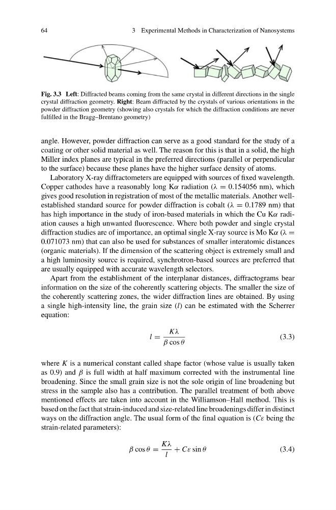
Fig. 3.3 Left: Diffracted beams coming from the same crystal in different directions in the single
crystal diffraction geometry. Right: Beam diffracted by the crystals of various orientations in the
powder diffraction geometry (showing also crystals for which the diffraction conditions are never
fulfilled in the Bragg–Brentano geometry)
angle. However, powder diffraction can serve as a good standard for the study of a
coating or other solid material as well. The reason for this is that in a solid, the high
Miller index planes are typical in the preferred directions (parallel or perpendicular
to the surface) because these planes have the higher surface density of atoms.
Laboratory X-ray diffractometers are equipped with sources of fixed wavelength.
Copper cathodes have a reasonably long Kα radiation (λ = 0.154056 nm), which
gives good resolution in registration of most of the metallic materials. Another wellestablished standard source for powder diffraction is cobalt (λ = 0.1789 nm) that
has high importance in the study of iron-based materials in which the Cu Kα radiation causes a high unwanted fluorescence. Where both powder and single crystal
diffraction studies are of importance, an optimal single X-ray source is Mo Kα (λ =
0.071073 nm) that can also be used for substances of smaller interatomic distances
(organic materials). If the dimension of the scattering object is extremely small and
a high luminosity source is required, synchrotron-based sources are preferred that
are usually equipped with accurate wavelength selectors.
Apart from the establishment of the interplanar distances, diffractograms bear
information on the size of the coherently scattering objects. The smaller the size of
the coherently scattering zones, the wider diffraction lines are obtained. By using
a single high-intensity line, the grain size (l) can be estimated with the Scherrer
equation:
l =
Kλ
β cos θ
(3.3)
where K is a numerical constant called shape factor (whose value is usually taken
as 0.9) and β is full width at half maximum corrected with the instrumental line
broadening. Since the small grain size is not the sole origin of line broadening but
stress in the sample also has a contribution. The parallel treatment of both above
mentioned effects are taken into account in the Williamson–Hall method. This is
based on the fact that strain-induced and size-related line broadenings differ in distinct
ways on the diffraction angle. The usual form of the final equation is (Cε being the
strain-related parameters):
β cos θ =
Kλ
l
+ Cε sin θ
(3.4)
3 Experimental Methods in Characterization of Nanosystems
Fig. 3.3 Left: Diffracted beams coming from the same crystal in different directions in the single
crystal diffraction geometry. Right: Beam diffracted by the crystals of various orientations in the
powder diffraction geometry (showing also crystals for which the diffraction conditions are never
fulfilled in the Bragg–Brentano geometry)
angle. However, powder diffraction can serve as a good standard for the study of a
coating or other solid material as well. The reason for this is that in a solid, the high
Miller index planes are typical in the preferred directions (parallel or perpendicular
to the surface) because these planes have the higher surface density of atoms.
Laboratory X-ray diffractometers are equipped with sources of fixed wavelength.
Copper cathodes have a reasonably long Kα radiation (λ = 0.154056 nm), which
gives good resolution in registration of most of the metallic materials. Another wellestablished standard source for powder diffraction is cobalt (λ = 0.1789 nm) that
has high importance in the study of iron-based materials in which the Cu Kα radiation causes a high unwanted fluorescence. Where both powder and single crystal
diffraction studies are of importance, an optimal single X-ray source is Mo Kα (λ =
0.071073 nm) that can also be used for substances of smaller interatomic distances
(organic materials). If the dimension of the scattering object is extremely small and
a high luminosity source is required, synchrotron-based sources are preferred that
are usually equipped with accurate wavelength selectors.
Apart from the establishment of the interplanar distances, diffractograms bear
information on the size of the coherently scattering objects. The smaller the size of
the coherently scattering zones, the wider diffraction lines are obtained. By using
a single high-intensity line, the grain size (l) can be estimated with the Scherrer
equation:
l =
Kλ
β cos θ
(3.3)
where K is a numerical constant called shape factor (whose value is usually taken
as 0.9) and β is full width at half maximum corrected with the instrumental line
broadening. Since the small grain size is not the sole origin of line broadening but
stress in the sample also has a contribution. The parallel treatment of both above
mentioned effects are taken into account in the Williamson–Hall method. This is
based on the fact that strain-induced and size-related line broadenings differ in distinct
ways on the diffraction angle. The usual form of the final equation is (Cε being the
strain-related parameters):
β cos θ =
Kλ
l
+ Cε sin θ
(3.4)