

3.2 Non-destructive Analysis Methods with Irradiation
63
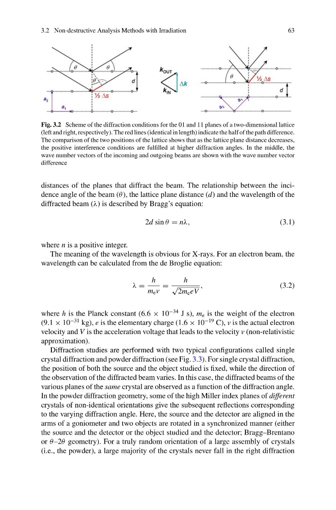
Fig. 3.2 Scheme of the diffraction conditions for the 01 and 11 planes of a two-dimensional lattice
(left and right, respectively). The red lines (identical in length) indicate the half of the path difference.
The comparison of the two positions of the lattice shows that as the lattice plane distance decreases,
the positive interference conditions are fulfilled at higher diffraction angles. In the middle, the
wave number vectors of the incoming and outgoing beams are shown with the wave number vector
difference
distances of the planes that diffract the beam. The relationship between the incidence angle of the beam (θ ), the lattice plane distance (d) and the wavelength of the
diffracted beam (λ) is described by Bragg’s equation:
2d sin θ = nλ,
(3.1)
where n is a positive integer.
The meaning of the wavelength is obvious for X-rays. For an electron beam, the
wavelength can be calculated from the de Broglie equation:
λ =
h
m e v
=
h
√
2m e eV
,
(3.2)
where h is the Planck constant (6.6 × 10
−34 J s), m e is the weight of the electron
(9.1 × 10
−31 kg), e is the elementary charge (1.6 × 10
−19 C), v is the actual electron
velocity and V is the acceleration voltage that leads to the velocity v (non-relativistic
approximation).
Diffraction studies are performed with two typical configurations called single
crystal diffraction and powder diffraction (see Fig. 3.3). For single crystal diffraction,
the position of both the source and the object studied is fixed, while the direction of
the observation of the diffracted beam varies. In this case, the diffracted beams of the
various planes of the same crystal are observed as a function of the diffraction angle.
In the powder diffraction geometry, some of the high Miller index planes of different
crystals of non-identical orientations give the subsequent reflections corresponding
to the varying diffraction angle. Here, the source and the detector are aligned in the
arms of a goniometer and two objects are rotated in a synchronized manner (either
the source and the detector or the object studied and the detector; Bragg–Brentano
or θ –2θ geometry). For a truly random orientation of a large assembly of crystals
(i.e., the powder), a large majority of the crystals never fall in the right diffraction
63
Fig. 3.2 Scheme of the diffraction conditions for the 01 and 11 planes of a two-dimensional lattice
(left and right, respectively). The red lines (identical in length) indicate the half of the path difference.
The comparison of the two positions of the lattice shows that as the lattice plane distance decreases,
the positive interference conditions are fulfilled at higher diffraction angles. In the middle, the
wave number vectors of the incoming and outgoing beams are shown with the wave number vector
difference
distances of the planes that diffract the beam. The relationship between the incidence angle of the beam (θ ), the lattice plane distance (d) and the wavelength of the
diffracted beam (λ) is described by Bragg’s equation:
2d sin θ = nλ,
(3.1)
where n is a positive integer.
The meaning of the wavelength is obvious for X-rays. For an electron beam, the
wavelength can be calculated from the de Broglie equation:
λ =
h
m e v
=
h
√
2m e eV
,
(3.2)
where h is the Planck constant (6.6 × 10
−34 J s), m e is the weight of the electron
(9.1 × 10
−31 kg), e is the elementary charge (1.6 × 10
−19 C), v is the actual electron
velocity and V is the acceleration voltage that leads to the velocity v (non-relativistic
approximation).
Diffraction studies are performed with two typical configurations called single
crystal diffraction and powder diffraction (see Fig. 3.3). For single crystal diffraction,
the position of both the source and the object studied is fixed, while the direction of
the observation of the diffracted beam varies. In this case, the diffracted beams of the
various planes of the same crystal are observed as a function of the diffraction angle.
In the powder diffraction geometry, some of the high Miller index planes of different
crystals of non-identical orientations give the subsequent reflections corresponding
to the varying diffraction angle. Here, the source and the detector are aligned in the
arms of a goniometer and two objects are rotated in a synchronized manner (either
the source and the detector or the object studied and the detector; Bragg–Brentano
or θ –2θ geometry). For a truly random orientation of a large assembly of crystals
(i.e., the powder), a large majority of the crystals never fall in the right diffraction