

364
11 Templated Systems
membranes, all others contain pores perpendicular to their surface. A comparison of
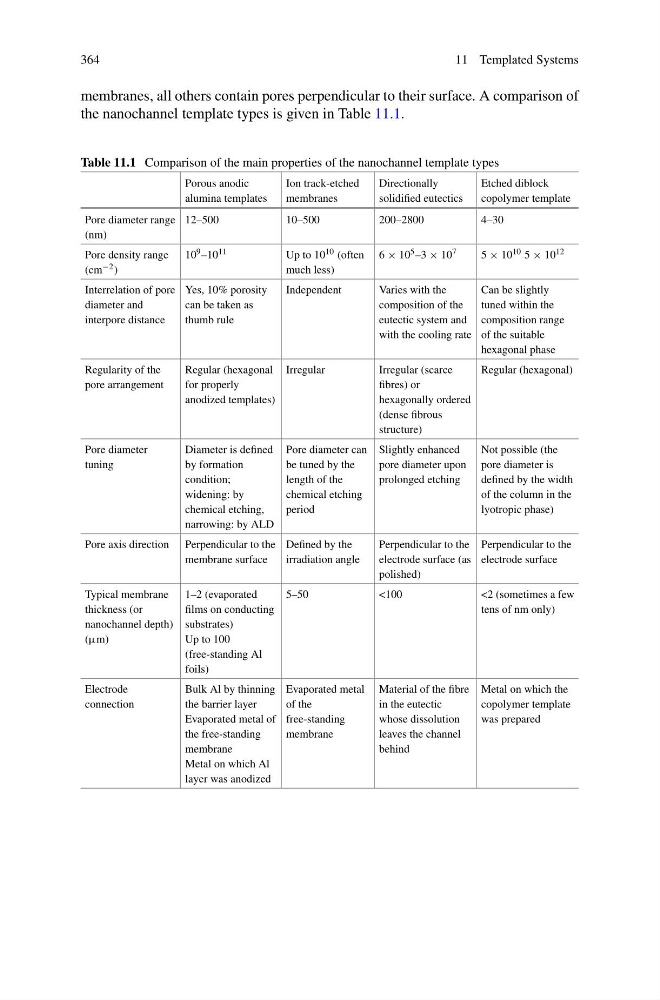
the nanochannel template types is given in Table 11.1.
Table 11.1 Comparison of the main properties of the nanochannel template types
Porous anodic
alumina templates
Ion track-etched
membranes
Directionally
solidified eutectics
Etched diblock
copolymer template
Pore diameter range
(nm)
12–500
10–500
200–2800
4–30
Pore density range
(cm −2 )
10 9 –10 11
Up to 10 10 (often
much less)
6 × 10 5 –3 × 10 7
5 × 10 10 5 × 10 12
Interrelation of pore
diameter and
interpore distance
Yes, 10% porosity
can be taken as
thumb rule
Independent
Varies with the
composition of the
eutectic system and
with the cooling rate
Can be slightly
tuned within the
composition range
of the suitable
hexagonal phase
Regularity of the
pore arrangement
Regular (hexagonal
for properly
anodized templates)
Irregular
Irregular (scarce
fibres) or
hexagonally ordered
(dense fibrous
structure)
Regular (hexagonal)
Pore diameter
tuning
Diameter is defined
by formation
condition;
widening: by
chemical etching,
narrowing: by ALD
Pore diameter can
be tuned by the
length of the
chemical etching
period
Slightly enhanced
pore diameter upon
prolonged etching
Not possible (the
pore diameter is
defined by the width
of the column in the
lyotropic phase)
Pore axis direction Perpendicular to the
membrane surface
Defined by the
irradiation angle
Perpendicular to the
electrode surface (as
polished)
Perpendicular to the
electrode surface
Typical membrane
thickness (or
nanochannel depth)
(μm)
1–2 (evaporated
films on conducting
substrates)
Up to 100
(free-standing Al
foils)
5–50
<100
<2 (sometimes a few
tens of nm only)
Electrode
connection
Bulk Al by thinning
the barrier layer
Evaporated metal of
the free-standing
membrane
Metal on which Al
layer was anodized
Evaporated metal
of the
free-standing
membrane
Material of the fibre
in the eutectic
whose dissolution
leaves the channel
behind
Metal on which the
copolymer template
was prepared
11 Templated Systems
membranes, all others contain pores perpendicular to their surface. A comparison of
the nanochannel template types is given in Table 11.1.
Table 11.1 Comparison of the main properties of the nanochannel template types
Porous anodic
alumina templates
Ion track-etched
membranes
Directionally
solidified eutectics
Etched diblock
copolymer template
Pore diameter range
(nm)
12–500
10–500
200–2800
4–30
Pore density range
(cm −2 )
10 9 –10 11
Up to 10 10 (often
much less)
6 × 10 5 –3 × 10 7
5 × 10 10 5 × 10 12
Interrelation of pore
diameter and
interpore distance
Yes, 10% porosity
can be taken as
thumb rule
Independent
Varies with the
composition of the
eutectic system and
with the cooling rate
Can be slightly
tuned within the
composition range
of the suitable
hexagonal phase
Regularity of the
pore arrangement
Regular (hexagonal
for properly
anodized templates)
Irregular
Irregular (scarce
fibres) or
hexagonally ordered
(dense fibrous
structure)
Regular (hexagonal)
Pore diameter
tuning
Diameter is defined
by formation
condition;
widening: by
chemical etching,
narrowing: by ALD
Pore diameter can
be tuned by the
length of the
chemical etching
period
Slightly enhanced
pore diameter upon
prolonged etching
Not possible (the
pore diameter is
defined by the width
of the column in the
lyotropic phase)
Pore axis direction Perpendicular to the
membrane surface
Defined by the
irradiation angle
Perpendicular to the
electrode surface (as
polished)
Perpendicular to the
electrode surface
Typical membrane
thickness (or
nanochannel depth)
(μm)
1–2 (evaporated
films on conducting
substrates)
Up to 100
(free-standing Al
foils)
5–50
<100
<2 (sometimes a few
tens of nm only)
Electrode
connection
Bulk Al by thinning
the barrier layer
Evaporated metal of
the free-standing
membrane
Metal on which Al
layer was anodized
Evaporated metal
of the
free-standing
membrane
Material of the fibre
in the eutectic
whose dissolution
leaves the channel
behind
Metal on which the
copolymer template
was prepared