

Numerical Dynamic Analysis of Gearbox Behaviour
435
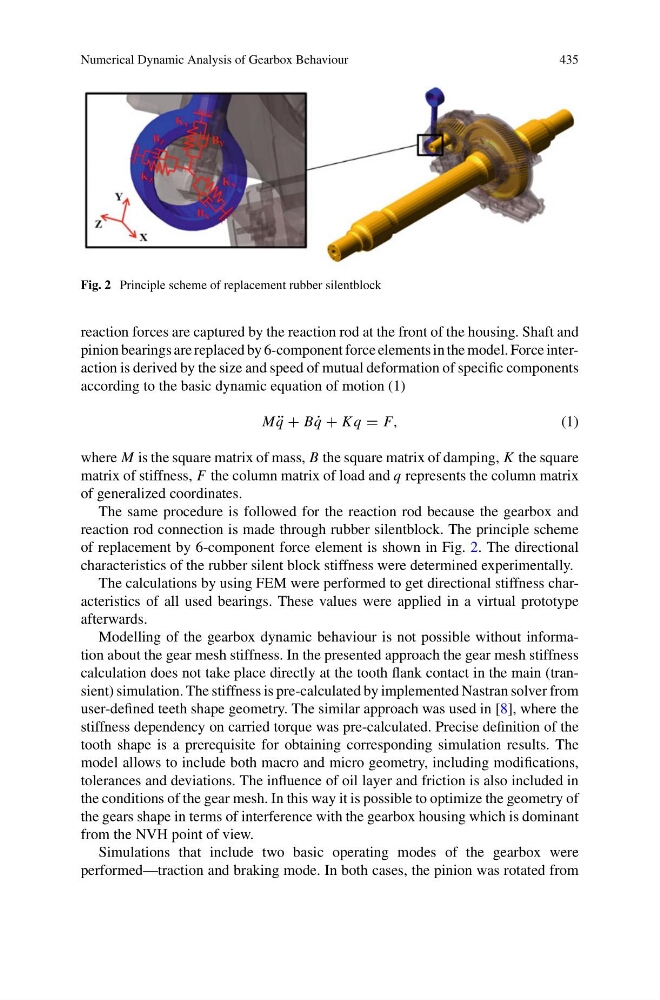
Fig. 2 Principle scheme of replacement rubber silentblock
reaction forces are captured by the reaction rod at the front of the housing. Shaft and
pinion bearings are replaced by 6-component force elements in the model. Force interaction is derived by the size and speed of mutual deformation of specific components
according to the basic dynamic equation of motion (1)
M ¨
q + B ˙
q + K q = F,
(1)
where M is the square matrix of mass, B the square matrix of damping, K the square
matrix of stiffness, F the column matrix of load and q represents the column matrix
of generalized coordinates.
The same procedure is followed for the reaction rod because the gearbox and
reaction rod connection is made through rubber silentblock. The principle scheme
of replacement by 6-component force element is shown in Fig. 2. The directional
characteristics of the rubber silent block stiffness were determined experimentally.
The calculations by using FEM were performed to get directional stiffness characteristics of all used bearings. These values were applied in a virtual prototype
afterwards.
Modelling of the gearbox dynamic behaviour is not possible without information about the gear mesh stiffness. In the presented approach the gear mesh stiffness
calculation does not take place directly at the tooth flank contact in the main (transient) simulation. The stiffness is pre-calculated by implemented Nastran solver from
user-defined teeth shape geometry. The similar approach was used in [8], where the
stiffness dependency on carried torque was pre-calculated. Precise definition of the
tooth shape is a prerequisite for obtaining corresponding simulation results. The
model allows to include both macro and micro geometry, including modifications,
tolerances and deviations. The influence of oil layer and friction is also included in
the conditions of the gear mesh. In this way it is possible to optimize the geometry of
the gears shape in terms of interference with the gearbox housing which is dominant
from the NVH point of view.
Simulations that include two basic operating modes of the gearbox were
performed—traction and braking mode. In both cases, the pinion was rotated from
435
Fig. 2 Principle scheme of replacement rubber silentblock
reaction forces are captured by the reaction rod at the front of the housing. Shaft and
pinion bearings are replaced by 6-component force elements in the model. Force interaction is derived by the size and speed of mutual deformation of specific components
according to the basic dynamic equation of motion (1)
M ¨
q + B ˙
q + K q = F,
(1)
where M is the square matrix of mass, B the square matrix of damping, K the square
matrix of stiffness, F the column matrix of load and q represents the column matrix
of generalized coordinates.
The same procedure is followed for the reaction rod because the gearbox and
reaction rod connection is made through rubber silentblock. The principle scheme
of replacement by 6-component force element is shown in Fig. 2. The directional
characteristics of the rubber silent block stiffness were determined experimentally.
The calculations by using FEM were performed to get directional stiffness characteristics of all used bearings. These values were applied in a virtual prototype
afterwards.
Modelling of the gearbox dynamic behaviour is not possible without information about the gear mesh stiffness. In the presented approach the gear mesh stiffness
calculation does not take place directly at the tooth flank contact in the main (transient) simulation. The stiffness is pre-calculated by implemented Nastran solver from
user-defined teeth shape geometry. The similar approach was used in [8], where the
stiffness dependency on carried torque was pre-calculated. Precise definition of the
tooth shape is a prerequisite for obtaining corresponding simulation results. The
model allows to include both macro and micro geometry, including modifications,
tolerances and deviations. The influence of oil layer and friction is also included in
the conditions of the gear mesh. In this way it is possible to optimize the geometry of
the gears shape in terms of interference with the gearbox housing which is dominant
from the NVH point of view.
Simulations that include two basic operating modes of the gearbox were
performed—traction and braking mode. In both cases, the pinion was rotated from