

434
V. Otipka et al.
to evaluate the acoustic performance of transmissions. This model can be used to
observe and compare the normal surface velocities at any location.
Transmission noise is the consequence of excited vibration of large transmission walls. The most important source of excitation remains the forces generated
by the gears meshing [5]. In principle, during the gear mesh, the stiffness of teeth
in contact is changing. This causes deviations from the ideal kinematics between
co-engaging gears–transmission error (TE) [6]. Teeth engage in a non-ideal position cause shocks and vibrations. Excitation frequencies are dependent on operating
conditions. Generally, these are wide frequency bands, which is necessary to deal
with.
2 Methods
The main part of the model is created in multi-body software Adams with including
plugin GearAT, while finite element software Ansys Workbench is used to obtain
some input data, like modal properties and bearing stiffness. In this case, the same
principle as in this paper [7] is used to obtain necessary input data from finite element
software.
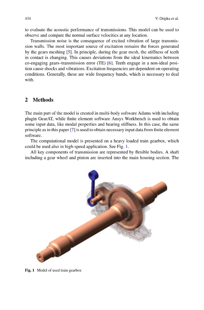
The computational model is presented on a heavy loaded train gearbox, which
could be used also in high-speed application. See Fig. 1.
All key components of transmission are represented by flexible bodies. A shaft
including a gear wheel and pinion are inserted into the main housing section. The
Fig. 1 Model of used train gearbox
V. Otipka et al.
to evaluate the acoustic performance of transmissions. This model can be used to
observe and compare the normal surface velocities at any location.
Transmission noise is the consequence of excited vibration of large transmission walls. The most important source of excitation remains the forces generated
by the gears meshing [5]. In principle, during the gear mesh, the stiffness of teeth
in contact is changing. This causes deviations from the ideal kinematics between
co-engaging gears–transmission error (TE) [6]. Teeth engage in a non-ideal position cause shocks and vibrations. Excitation frequencies are dependent on operating
conditions. Generally, these are wide frequency bands, which is necessary to deal
with.
2 Methods
The main part of the model is created in multi-body software Adams with including
plugin GearAT, while finite element software Ansys Workbench is used to obtain
some input data, like modal properties and bearing stiffness. In this case, the same
principle as in this paper [7] is used to obtain necessary input data from finite element
software.
The computational model is presented on a heavy loaded train gearbox, which
could be used also in high-speed application. See Fig. 1.
All key components of transmission are represented by flexible bodies. A shaft
including a gear wheel and pinion are inserted into the main housing section. The
Fig. 1 Model of used train gearbox