

ANN Samples Generation Using 2D Dynamic …
391
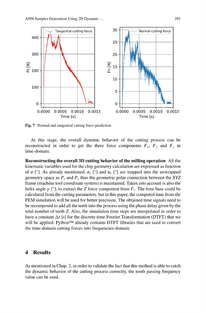
Fig. 7 Normal and tangential cutting force prediction
At this stage, the overall dynamic behavior of the cutting process can be
reconstructed in order to get the three force components F x , F y and F z in
time-domain.
Reconstructing the overall 3D cutting behavior of the milling operation All the
kinematic variables used for the chip geometry calculation are expressed as function
of ø [°]. As already mentioned, ø s [°] and ø e [°] are mapped into the unwrapped
geometry space as P s and P e thus the geometric polar connection between the XYZ
frame (machine tool coordinate system) is maintained. Taken into account is also the
helix angle γ [°], to extract the Z force component from F t . The time base could be
calculated from the cutting parameters, but in this paper, the computed time from the
FEM simulation will be used for better precision. The obtained time signals need to
be recomposed to add all the teeth into the process using the phase delay given by the
total number of teeth Z. Also, the simulation time steps are interpolated in order to
have a constant t [s] for the discrete-time Fourier Transformation (DTFT) that we
will be applied. Python™ already contains DTFT libraries that are used to convert
the time-domain cutting forces into frequencies-domain.
4 Results
As mentioned in Chap. 2, in order to validate the fact that this method is able to catch
the dynamic behavior of the cutting process correctly, the tooth passing frequency
value can be used.
391
Fig. 7 Normal and tangential cutting force prediction
At this stage, the overall dynamic behavior of the cutting process can be
reconstructed in order to get the three force components F x , F y and F z in
time-domain.
Reconstructing the overall 3D cutting behavior of the milling operation All the
kinematic variables used for the chip geometry calculation are expressed as function
of ø [°]. As already mentioned, ø s [°] and ø e [°] are mapped into the unwrapped
geometry space as P s and P e thus the geometric polar connection between the XYZ
frame (machine tool coordinate system) is maintained. Taken into account is also the
helix angle γ [°], to extract the Z force component from F t . The time base could be
calculated from the cutting parameters, but in this paper, the computed time from the
FEM simulation will be used for better precision. The obtained time signals need to
be recomposed to add all the teeth into the process using the phase delay given by the
total number of teeth Z. Also, the simulation time steps are interpolated in order to
have a constant t [s] for the discrete-time Fourier Transformation (DTFT) that we
will be applied. Python™ already contains DTFT libraries that are used to convert
the time-domain cutting forces into frequencies-domain.
4 Results
As mentioned in Chap. 2, in order to validate the fact that this method is able to catch
the dynamic behavior of the cutting process correctly, the tooth passing frequency
value can be used.