

392
A.-I. Berariu et al.
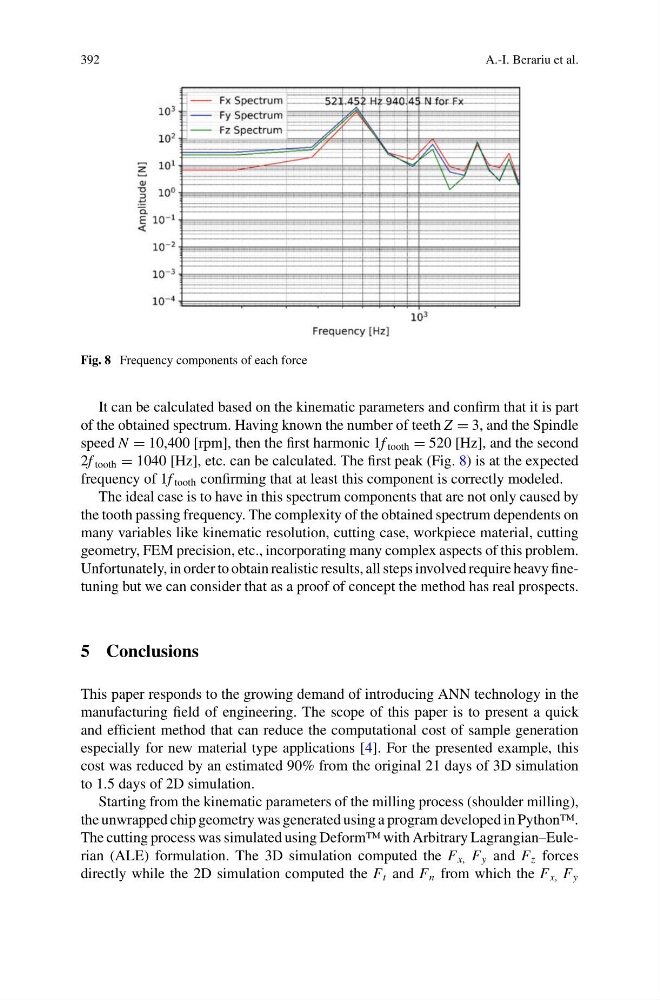
Fig. 8 Frequency components of each force
It can be calculated based on the kinematic parameters and confirm that it is part
of the obtained spectrum. Having known the number of teeth Z = 3, and the Spindle
speed N = 10,400 [rpm], then the first harmonic 1f tooth = 520 [Hz], and the second
2f tooth = 1040 [Hz], etc. can be calculated. The first peak (Fig. 8) is at the expected
frequency of 1f tooth confirming that at least this component is correctly modeled.
The ideal case is to have in this spectrum components that are not only caused by
the tooth passing frequency. The complexity of the obtained spectrum dependents on
many variables like kinematic resolution, cutting case, workpiece material, cutting
geometry, FEM precision, etc., incorporating many complex aspects of this problem.
Unfortunately, in order to obtain realistic results, all steps involved require heavy finetuning but we can consider that as a proof of concept the method has real prospects.
5 Conclusions
This paper responds to the growing demand of introducing ANN technology in the
manufacturing field of engineering. The scope of this paper is to present a quick
and efficient method that can reduce the computational cost of sample generation
especially for new material type applications [4]. For the presented example, this
cost was reduced by an estimated 90% from the original 21 days of 3D simulation
to 1.5 days of 2D simulation.
Starting from the kinematic parameters of the milling process (shoulder milling),
the unwrapped chip geometry was generated using a program developed in Python™.
The cutting process was simulated using Deform™ with Arbitrary Lagrangian–Eulerian (ALE) formulation. The 3D simulation computed the F x, F y and F z forces
directly while the 2D simulation computed the F t and F n from which the F x, F y
A.-I. Berariu et al.
Fig. 8 Frequency components of each force
It can be calculated based on the kinematic parameters and confirm that it is part
of the obtained spectrum. Having known the number of teeth Z = 3, and the Spindle
speed N = 10,400 [rpm], then the first harmonic 1f tooth = 520 [Hz], and the second
2f tooth = 1040 [Hz], etc. can be calculated. The first peak (Fig. 8) is at the expected
frequency of 1f tooth confirming that at least this component is correctly modeled.
The ideal case is to have in this spectrum components that are not only caused by
the tooth passing frequency. The complexity of the obtained spectrum dependents on
many variables like kinematic resolution, cutting case, workpiece material, cutting
geometry, FEM precision, etc., incorporating many complex aspects of this problem.
Unfortunately, in order to obtain realistic results, all steps involved require heavy finetuning but we can consider that as a proof of concept the method has real prospects.
5 Conclusions
This paper responds to the growing demand of introducing ANN technology in the
manufacturing field of engineering. The scope of this paper is to present a quick
and efficient method that can reduce the computational cost of sample generation
especially for new material type applications [4]. For the presented example, this
cost was reduced by an estimated 90% from the original 21 days of 3D simulation
to 1.5 days of 2D simulation.
Starting from the kinematic parameters of the milling process (shoulder milling),
the unwrapped chip geometry was generated using a program developed in Python™.
The cutting process was simulated using Deform™ with Arbitrary Lagrangian–Eulerian (ALE) formulation. The 3D simulation computed the F x, F y and F z forces
directly while the 2D simulation computed the F t and F n from which the F x, F y