

ANN Samples Generation Using 2D Dynamic …
389
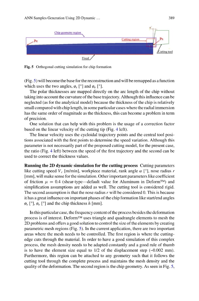
Fig. 5 Orthogonal cutting simulation for chip formation
(Fig. 5) will become the base for the reconstruction and will be remapped as a function
which uses the two angles, ø s [°] and ø e [°].
The polar thicknesses are mapped directly on the arc length of the chip without
taking into account the curvature of the base trajectory. Although this influence can be
neglected (as for the analytical model) because the thickness of the chip is relatively
small compared with chip length, in some particular cases where the radial immersion
has the same order of magnitude as the thickness, this can become a problem in term
of precision.
One solution that can help with this problem is the usage of a correction factor
based on the linear velocity of the cutting tip (Fig. 4 left).
The linear velocity uses the cycloidal trajectory points and the central tool positions associated with the first points to determine the speed variation. Although this
parameter is not necessarily part of the proposed cutting model, for the present case,
the ratio (Fig. 4 left) between the speed of the first trajectory and the second can be
used to correct the thickness values.
Running the 2D dynamic simulation for the cutting process Cutting parameters
like cutting speed V c [m/min], workpiece material, rank angle α [°], nose radius r
[mm], will make sense for the simulation. Other important parameters like coefficient
of friction μ = 0.4 (shear-type—default value for Aluminum in Deform™) and
simplification assumptions are added as well. The cutting tool is considered rigid.
The second assumption is that the nose radius r will be considered 0. This is because
it has a great influence on important phases of the chip formation like start/end angles
ø s [°], ø e [°] and the chip thickness h [mm].
In this particular case, the frequency content of the process besides the deformation
process is of interest. Deform™ uses triangle and quadrangle elements to mesh the
2D problems and offers a good solution to control the size of the elements by creating
parametric mesh regions (Fig. 5). In the current application, there are two important
areas where the mesh needs to be controlled. The first region is where the cuttingedge cuts through the material. In order to have a good simulation of this complex
process, the mesh density needs to be adapted constantly and a good rule of thumb
is to have the element size equal to 1/2 of the displacement step (~0.002 mm).
Furthermore, this region can be attached to any geometry such that it follows the
cutting tool through the complete process and maintains the mesh density and the
quality of the deformation. The second region is the chip geometry. As seen in Fig. 5,
389
Fig. 5 Orthogonal cutting simulation for chip formation
(Fig. 5) will become the base for the reconstruction and will be remapped as a function
which uses the two angles, ø s [°] and ø e [°].
The polar thicknesses are mapped directly on the arc length of the chip without
taking into account the curvature of the base trajectory. Although this influence can be
neglected (as for the analytical model) because the thickness of the chip is relatively
small compared with chip length, in some particular cases where the radial immersion
has the same order of magnitude as the thickness, this can become a problem in term
of precision.
One solution that can help with this problem is the usage of a correction factor
based on the linear velocity of the cutting tip (Fig. 4 left).
The linear velocity uses the cycloidal trajectory points and the central tool positions associated with the first points to determine the speed variation. Although this
parameter is not necessarily part of the proposed cutting model, for the present case,
the ratio (Fig. 4 left) between the speed of the first trajectory and the second can be
used to correct the thickness values.
Running the 2D dynamic simulation for the cutting process Cutting parameters
like cutting speed V c [m/min], workpiece material, rank angle α [°], nose radius r
[mm], will make sense for the simulation. Other important parameters like coefficient
of friction μ = 0.4 (shear-type—default value for Aluminum in Deform™) and
simplification assumptions are added as well. The cutting tool is considered rigid.
The second assumption is that the nose radius r will be considered 0. This is because
it has a great influence on important phases of the chip formation like start/end angles
ø s [°], ø e [°] and the chip thickness h [mm].
In this particular case, the frequency content of the process besides the deformation
process is of interest. Deform™ uses triangle and quadrangle elements to mesh the
2D problems and offers a good solution to control the size of the elements by creating
parametric mesh regions (Fig. 5). In the current application, there are two important
areas where the mesh needs to be controlled. The first region is where the cuttingedge cuts through the material. In order to have a good simulation of this complex
process, the mesh density needs to be adapted constantly and a good rule of thumb
is to have the element size equal to 1/2 of the displacement step (~0.002 mm).
Furthermore, this region can be attached to any geometry such that it follows the
cutting tool through the complete process and maintains the mesh density and the
quality of the deformation. The second region is the chip geometry. As seen in Fig. 5,