

388
A.-I. Berariu et al.
A real cutting case is used, where the same material (Al6061_Machining) is premachined with the following cutting values: cutting speed Vc = 588 [m/min], feed
per tooth V z = 0.25 [mm], cutting diameter D c = 18 [mm] and clockwise rotation.
Next step is defining the workpiece perimeter (boundary definition vs. trajectories)
in order to detect the locations where the cutting tool will start cutting, ø s [°], and
where it will exit the cutting ø e [°] (Fig. 3).
Worth mentioning is that for the definition of the start/end points, the intersections
between the workpiece boundary and the trajectory of the second tooth will be used,
the reason being that this curve will be used as a base for the unwrapping process and
each section of the chip will be defined based on this curve and the first. Also, this
method is applicable only for the cases where the chip length is constant (stationary
phase where the same chip geometry is removed by each tooth).
The final phase for the unwrapping process is the chip sectioning. The sectioning
lines as a function of ø[°] need to be defined. The reason is that the radial origin needs
to move while rotating (Fig. 3) and connect each position with the correct point of
reference located on the second tooth trajectory (the one that will become the base
for the unwrapping).
After the sections are defined, the last step is to intersect the new lines with the
first trajectory (first tooth) and measure the distances for each pair of points. The
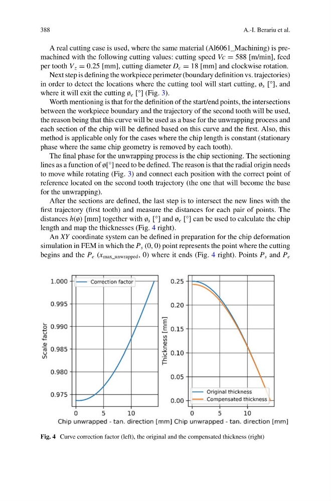
distances h(ø) [mm] together with ø s [°] and ø e [°] can be used to calculate the chip
length and map the thicknesses (Fig. 4 right).
An XY coordinate system can be defined in preparation for the chip deformation
simulation in FEM in which the P s (0, 0) point represents the point where the cutting
begins and the P e (x max_unwrapped , 0) where it ends (Fig. 4 right). Points P s and P e
Fig. 4 Curve correction factor (left), the original and the compensated thickness (right)
A.-I. Berariu et al.
A real cutting case is used, where the same material (Al6061_Machining) is premachined with the following cutting values: cutting speed Vc = 588 [m/min], feed
per tooth V z = 0.25 [mm], cutting diameter D c = 18 [mm] and clockwise rotation.
Next step is defining the workpiece perimeter (boundary definition vs. trajectories)
in order to detect the locations where the cutting tool will start cutting, ø s [°], and
where it will exit the cutting ø e [°] (Fig. 3).
Worth mentioning is that for the definition of the start/end points, the intersections
between the workpiece boundary and the trajectory of the second tooth will be used,
the reason being that this curve will be used as a base for the unwrapping process and
each section of the chip will be defined based on this curve and the first. Also, this
method is applicable only for the cases where the chip length is constant (stationary
phase where the same chip geometry is removed by each tooth).
The final phase for the unwrapping process is the chip sectioning. The sectioning
lines as a function of ø[°] need to be defined. The reason is that the radial origin needs
to move while rotating (Fig. 3) and connect each position with the correct point of
reference located on the second tooth trajectory (the one that will become the base
for the unwrapping).
After the sections are defined, the last step is to intersect the new lines with the
first trajectory (first tooth) and measure the distances for each pair of points. The
distances h(ø) [mm] together with ø s [°] and ø e [°] can be used to calculate the chip
length and map the thicknesses (Fig. 4 right).
An XY coordinate system can be defined in preparation for the chip deformation
simulation in FEM in which the P s (0, 0) point represents the point where the cutting
begins and the P e (x max_unwrapped , 0) where it ends (Fig. 4 right). Points P s and P e
Fig. 4 Curve correction factor (left), the original and the compensated thickness (right)