

386
A.-I. Berariu et al.
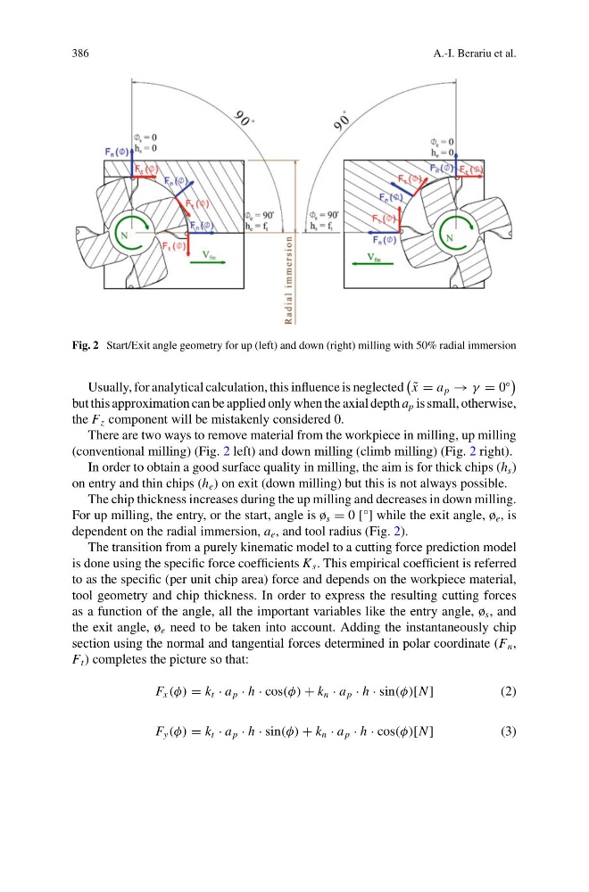
Fig. 2 Start/Exit angle geometry for up (left) and down (right) milling with 50% radial immersion
Usually, for analytical calculation, this influence is neglected
˜
x = a p → γ = 0
◦
but this approximation can be applied only when the axial depth a p is small, otherwise,
the F z component will be mistakenly considered 0.
There are two ways to remove material from the workpiece in milling, up milling
(conventional milling) (Fig. 2 left) and down milling (climb milling) (Fig. 2 right).
In order to obtain a good surface quality in milling, the aim is for thick chips (h s )
on entry and thin chips (h e ) on exit (down milling) but this is not always possible.
The chip thickness increases during the up milling and decreases in down milling.
For up milling, the entry, or the start, angle is ø s = 0 [°] while the exit angle, ø e , is
dependent on the radial immersion, a e , and tool radius (Fig. 2).
The transition from a purely kinematic model to a cutting force prediction model
is done using the specific force coefficients K s . This empirical coefficient is referred
to as the specific (per unit chip area) force and depends on the workpiece material,
tool geometry and chip thickness. In order to express the resulting cutting forces
as a function of the angle, all the important variables like the entry angle, ø s , and
the exit angle, ø e need to be taken into account. Adding the instantaneously chip
section using the normal and tangential forces determined in polar coordinate (F n ,
F t ) completes the picture so that:
F x (φ) = k t · a p · h · cos(φ) + k n · a p · h · sin(φ)[N ]
(2)
F y (φ) = k t · a p · h · sin(φ) + k n · a p · h · cos(φ)[N ]
(3)
A.-I. Berariu et al.
Fig. 2 Start/Exit angle geometry for up (left) and down (right) milling with 50% radial immersion
Usually, for analytical calculation, this influence is neglected
˜
x = a p → γ = 0
◦
but this approximation can be applied only when the axial depth a p is small, otherwise,
the F z component will be mistakenly considered 0.
There are two ways to remove material from the workpiece in milling, up milling
(conventional milling) (Fig. 2 left) and down milling (climb milling) (Fig. 2 right).
In order to obtain a good surface quality in milling, the aim is for thick chips (h s )
on entry and thin chips (h e ) on exit (down milling) but this is not always possible.
The chip thickness increases during the up milling and decreases in down milling.
For up milling, the entry, or the start, angle is ø s = 0 [°] while the exit angle, ø e , is
dependent on the radial immersion, a e , and tool radius (Fig. 2).
The transition from a purely kinematic model to a cutting force prediction model
is done using the specific force coefficients K s . This empirical coefficient is referred
to as the specific (per unit chip area) force and depends on the workpiece material,
tool geometry and chip thickness. In order to express the resulting cutting forces
as a function of the angle, all the important variables like the entry angle, ø s , and
the exit angle, ø e need to be taken into account. Adding the instantaneously chip
section using the normal and tangential forces determined in polar coordinate (F n ,
F t ) completes the picture so that:
F x (φ) = k t · a p · h · cos(φ) + k n · a p · h · sin(φ)[N ]
(2)
F y (φ) = k t · a p · h · sin(φ) + k n · a p · h · cos(φ)[N ]
(3)