

ANN Samples Generation Using 2D Dynamic …
385
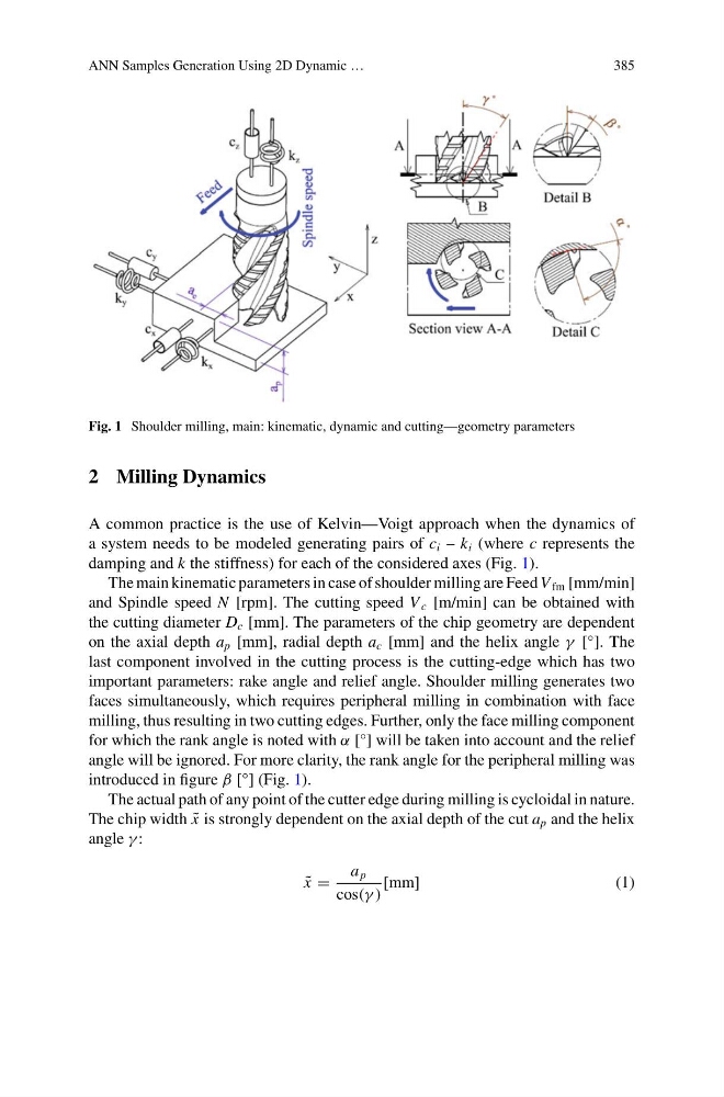
Fig. 1 Shoulder milling, main: kinematic, dynamic and cutting—geometry parameters
2 Milling Dynamics
A common practice is the use of Kelvin—Voigt approach when the dynamics of
a system needs to be modeled generating pairs of c i – k i (where c represents the
damping and k the stiffness) for each of the considered axes (Fig. 1).
The main kinematic parameters in case of shoulder milling are Feed V fm [mm/min]
and Spindle speed N [rpm]. The cutting speed V c [m/min] can be obtained with
the cutting diameter D c [mm]. The parameters of the chip geometry are dependent
on the axial depth a p [mm], radial depth a c [mm] and the helix angle γ [°]. The
last component involved in the cutting process is the cutting-edge which has two
important parameters: rake angle and relief angle. Shoulder milling generates two
faces simultaneously, which requires peripheral milling in combination with face
milling, thus resulting in two cutting edges. Further, only the face milling component
for which the rank angle is noted with α [°] will be taken into account and the relief
angle will be ignored. For more clarity, the rank angle for the peripheral milling was
introduced in figure β [°] (Fig. 1).
The actual path of any point of the cutter edge during milling is cycloidal in nature.
The chip width ˜
x is strongly dependent on the axial depth of the cut a p and the helix
angle γ :
˜
x =
a p
cos(γ )
[mm]
(1)
385
Fig. 1 Shoulder milling, main: kinematic, dynamic and cutting—geometry parameters
2 Milling Dynamics
A common practice is the use of Kelvin—Voigt approach when the dynamics of
a system needs to be modeled generating pairs of c i – k i (where c represents the
damping and k the stiffness) for each of the considered axes (Fig. 1).
The main kinematic parameters in case of shoulder milling are Feed V fm [mm/min]
and Spindle speed N [rpm]. The cutting speed V c [m/min] can be obtained with
the cutting diameter D c [mm]. The parameters of the chip geometry are dependent
on the axial depth a p [mm], radial depth a c [mm] and the helix angle γ [°]. The
last component involved in the cutting process is the cutting-edge which has two
important parameters: rake angle and relief angle. Shoulder milling generates two
faces simultaneously, which requires peripheral milling in combination with face
milling, thus resulting in two cutting edges. Further, only the face milling component
for which the rank angle is noted with α [°] will be taken into account and the relief
angle will be ignored. For more clarity, the rank angle for the peripheral milling was
introduced in figure β [°] (Fig. 1).
The actual path of any point of the cutter edge during milling is cycloidal in nature.
The chip width ˜
x is strongly dependent on the axial depth of the cut a p and the helix
angle γ :
˜
x =
a p
cos(γ )
[mm]
(1)