

New Medical Rehabilitation System
271
From a structural point of view, the rehabilitation mechanism consists of six
movable elements and one element fixed (respectively 7), with four rotations and
one translation. We applied the (2) for calculating mobility
M = 6n −
5
m=1
m ∗ C m
(2)
where
n represents the number of mobile elements,
C m is the number of pair elements,
m is the number of constraints.
The degree of mobility is (2) and highlights the number of independent elements
that define the status parameters of the mechanism. We will consider two distinct
solutions, one where the elements (3) and (4) are parallel and another solution when
we have a knee rotation in point E.
The contour equalization can be rewritten using Fig. 3b:
AB + BC + CD + DA = 0
( 3 )
AB + BC + CE + EF + FG = AP + PG
(4)
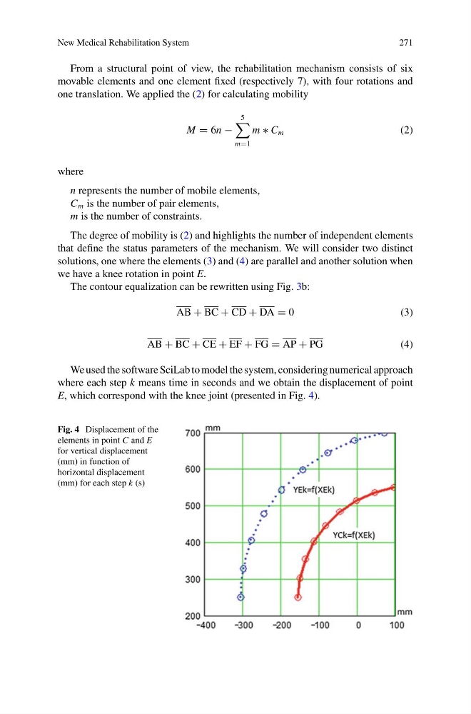
We used the software SciLab to model the system, considering numerical approach
where each step k means time in seconds and we obtain the displacement of point
E, which correspond with the knee joint (presented in Fig. 4).
Fig. 4 Displacement of the
elements in point C and E
for vertical displacement
(mm) in function of
horizontal displacement
(mm) for each step k (s)
271
From a structural point of view, the rehabilitation mechanism consists of six
movable elements and one element fixed (respectively 7), with four rotations and
one translation. We applied the (2) for calculating mobility
M = 6n −
5
m=1
m ∗ C m
(2)
where
n represents the number of mobile elements,
C m is the number of pair elements,
m is the number of constraints.
The degree of mobility is (2) and highlights the number of independent elements
that define the status parameters of the mechanism. We will consider two distinct
solutions, one where the elements (3) and (4) are parallel and another solution when
we have a knee rotation in point E.
The contour equalization can be rewritten using Fig. 3b:
AB + BC + CD + DA = 0
( 3 )
AB + BC + CE + EF + FG = AP + PG
(4)
We used the software SciLab to model the system, considering numerical approach
where each step k means time in seconds and we obtain the displacement of point
E, which correspond with the knee joint (presented in Fig. 4).
Fig. 4 Displacement of the
elements in point C and E
for vertical displacement
(mm) in function of
horizontal displacement
(mm) for each step k (s)