

272
C.-G. Alionte et al.
a)
b)
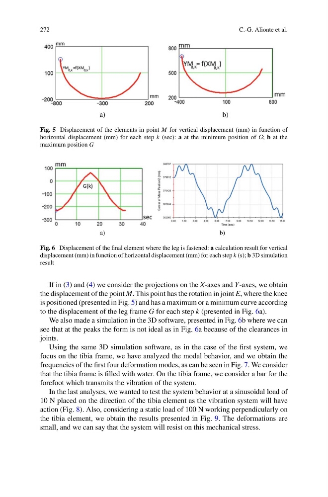
Fig. 5 Displacement of the elements in point M for vertical displacement (mm) in function of
horizontal displacement (mm) for each step k (sec): a at the minimum position of G; b at the
maximum position G
a)
b)
Fig. 6 Displacement of the final element where the leg is fastened: a calculation result for vertical
displacement (mm) in function of horizontal displacement (mm) for each step k (s); b 3D simulation
result
If in (3) and (4) we consider the projections on the X-axes and Y-axes, we obtain
the displacement of the point M. This point has the rotation in joint E, where the knee
is positioned (presented in Fig. 5) and has a maximum or a minimum curve according
to the displacement of the leg frame G for each step k (presented in Fig. 6a).
We also made a simulation in the 3D software, presented in Fig. 6b where we can
see that at the peaks the form is not ideal as in Fig. 6a because of the clearances in
joints.
Using the same 3D simulation software, as in the case of the first system, we
focus on the tibia frame, we have analyzed the modal behavior, and we obtain the
frequencies of the first four deformation modes, as can be seen in Fig. 7. We consider
that the tibia frame is filled with water. On the tibia frame, we consider a bar for the
forefoot which transmits the vibration of the system.
In the last analyses, we wanted to test the system behavior at a sinusoidal load of
10 N placed on the direction of the tibia element as the vibration system will have
action (Fig. 8). Also, considering a static load of 100 N working perpendicularly on
the tibia element, we obtain the results presented in Fig. 9. The deformations are
small, and we can say that the system will resist on this mechanical stress.
C.-G. Alionte et al.
a)
b)
Fig. 5 Displacement of the elements in point M for vertical displacement (mm) in function of
horizontal displacement (mm) for each step k (sec): a at the minimum position of G; b at the
maximum position G
a)
b)
Fig. 6 Displacement of the final element where the leg is fastened: a calculation result for vertical
displacement (mm) in function of horizontal displacement (mm) for each step k (s); b 3D simulation
result
If in (3) and (4) we consider the projections on the X-axes and Y-axes, we obtain
the displacement of the point M. This point has the rotation in joint E, where the knee
is positioned (presented in Fig. 5) and has a maximum or a minimum curve according
to the displacement of the leg frame G for each step k (presented in Fig. 6a).
We also made a simulation in the 3D software, presented in Fig. 6b where we can
see that at the peaks the form is not ideal as in Fig. 6a because of the clearances in
joints.
Using the same 3D simulation software, as in the case of the first system, we
focus on the tibia frame, we have analyzed the modal behavior, and we obtain the
frequencies of the first four deformation modes, as can be seen in Fig. 7. We consider
that the tibia frame is filled with water. On the tibia frame, we consider a bar for the
forefoot which transmits the vibration of the system.
In the last analyses, we wanted to test the system behavior at a sinusoidal load of
10 N placed on the direction of the tibia element as the vibration system will have
action (Fig. 8). Also, considering a static load of 100 N working perpendicularly on
the tibia element, we obtain the results presented in Fig. 9. The deformations are
small, and we can say that the system will resist on this mechanical stress.