

160
N. Bogojevi´ c et al.
r ϕ =
Z
cos ϕ + 1
Z cos ϕ − 1
(9)
Z
= Z
c coth γ d
(10)
Z
c =
Z c
ρ 0 c 0
(11)
with the following designations:
ϕ angle of incidence, in radians,
α ϕ the absorption coefficient for a plane sound wave bound to the angle ϕ,
r ϕ reflection coefficient for a plane sound wave bound to the angle ϕ,
Z
normalized surface impedance of the sample
Z
c normalized characteristic impedance of absorbent material,
d sample thickness
4 Results and Discussion
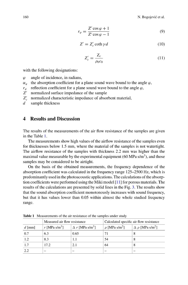
The results of the measurements of the air flow resistance of the samples are given
in the Table 1.
The measurements show high values of the airflow resistance of the samples even
for thicknesses below 1.5 mm, where the material of the samples is not watertight.
The airflow resistance of the samples with thickness 2.2 mm was higher than the
maximal value measurable by the experimental equipment (60 MPa s/m
3 ), and those
samples may be considered to be airtight.
On the basis of the obtained measurements, the frequency dependence of the
absorption coefficient was calculated in the frequency range 125–2500 Hz, which is
predominantly used in the photoacoustic applications. The calculations of the absorption coefficients were performed using the Miki model [11] for porous materials. The
results of the calculations are presented by solid lines in the Fig. 3. The results show
that the sound absorption coefficient monotonously increases with sound frequency,
but that it has values lower than 0.05 within almost the whole studied frequency
range.
Table 1 Measurements of the air resistance of the samples under study
Measured air flow resistance
Calculated specific air flow resistance
d [mm]
r [MPa s/m 3 ]
r [MPa s/m 3 ]
ρ [MPa s/m 2 ]
ρ [MPa s/m 2 ]
0.7
6.3
0.65
71
8
1.2
8.3
1.1
54
8
1.7
17.2
2.1
64
8
2.2
–
–
–
–
N. Bogojevi´ c et al.
r ϕ =
Z
cos ϕ + 1
Z cos ϕ − 1
(9)
Z
= Z
c coth γ d
(10)
Z
c =
Z c
ρ 0 c 0
(11)
with the following designations:
ϕ angle of incidence, in radians,
α ϕ the absorption coefficient for a plane sound wave bound to the angle ϕ,
r ϕ reflection coefficient for a plane sound wave bound to the angle ϕ,
Z
normalized surface impedance of the sample
Z
c normalized characteristic impedance of absorbent material,
d sample thickness
4 Results and Discussion
The results of the measurements of the air flow resistance of the samples are given
in the Table 1.
The measurements show high values of the airflow resistance of the samples even
for thicknesses below 1.5 mm, where the material of the samples is not watertight.
The airflow resistance of the samples with thickness 2.2 mm was higher than the
maximal value measurable by the experimental equipment (60 MPa s/m
3 ), and those
samples may be considered to be airtight.
On the basis of the obtained measurements, the frequency dependence of the
absorption coefficient was calculated in the frequency range 125–2500 Hz, which is
predominantly used in the photoacoustic applications. The calculations of the absorption coefficients were performed using the Miki model [11] for porous materials. The
results of the calculations are presented by solid lines in the Fig. 3. The results show
that the sound absorption coefficient monotonously increases with sound frequency,
but that it has values lower than 0.05 within almost the whole studied frequency
range.
Table 1 Measurements of the air resistance of the samples under study
Measured air flow resistance
Calculated specific air flow resistance
d [mm]
r [MPa s/m 3 ]
r [MPa s/m 3 ]
ρ [MPa s/m 2 ]
ρ [MPa s/m 2 ]
0.7
6.3
0.65
71
8
1.2
8.3
1.1
54
8
1.7
17.2
2.1
64
8
2.2
–
–
–
–