

96
V. Ionica et al.
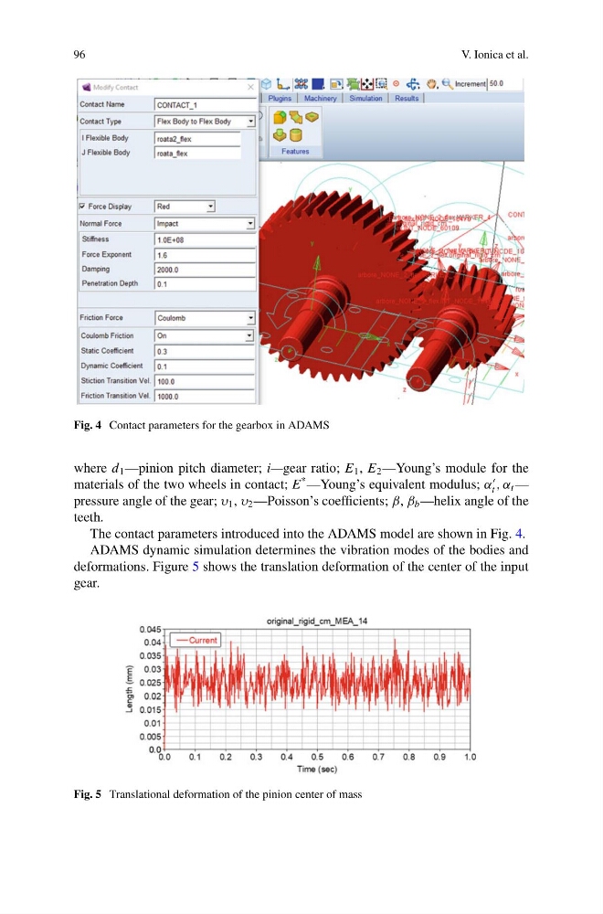
Fig. 4 Contact parameters for the gearbox in ADAMS
where d 1 —pinion pitch diameter; i—gear ratio; E 1 , E 2 —Young’s module for the
materials of the two wheels in contact; E
* —Young’s equivalent modulus; α
t , α t —
pressure angle of the gear; υ 1 , υ 2 —Poisson’s coefficients; β, β b —helix angle of the
teeth.
The contact parameters introduced into the ADAMS model are shown in Fig. 4.
ADAMS dynamic simulation determines the vibration modes of the bodies and
deformations. Figure 5 shows the translation deformation of the center of the input
gear.
Fig. 5 Translational deformation of the pinion center of mass
V. Ionica et al.
Fig. 4 Contact parameters for the gearbox in ADAMS
where d 1 —pinion pitch diameter; i—gear ratio; E 1 , E 2 —Young’s module for the
materials of the two wheels in contact; E
* —Young’s equivalent modulus; α
t , α t —
pressure angle of the gear; υ 1 , υ 2 —Poisson’s coefficients; β, β b —helix angle of the
teeth.
The contact parameters introduced into the ADAMS model are shown in Fig. 4.
ADAMS dynamic simulation determines the vibration modes of the bodies and
deformations. Figure 5 shows the translation deformation of the center of the input
gear.
Fig. 5 Translational deformation of the pinion center of mass