

Gears Dynamic Response to Vibrations
97
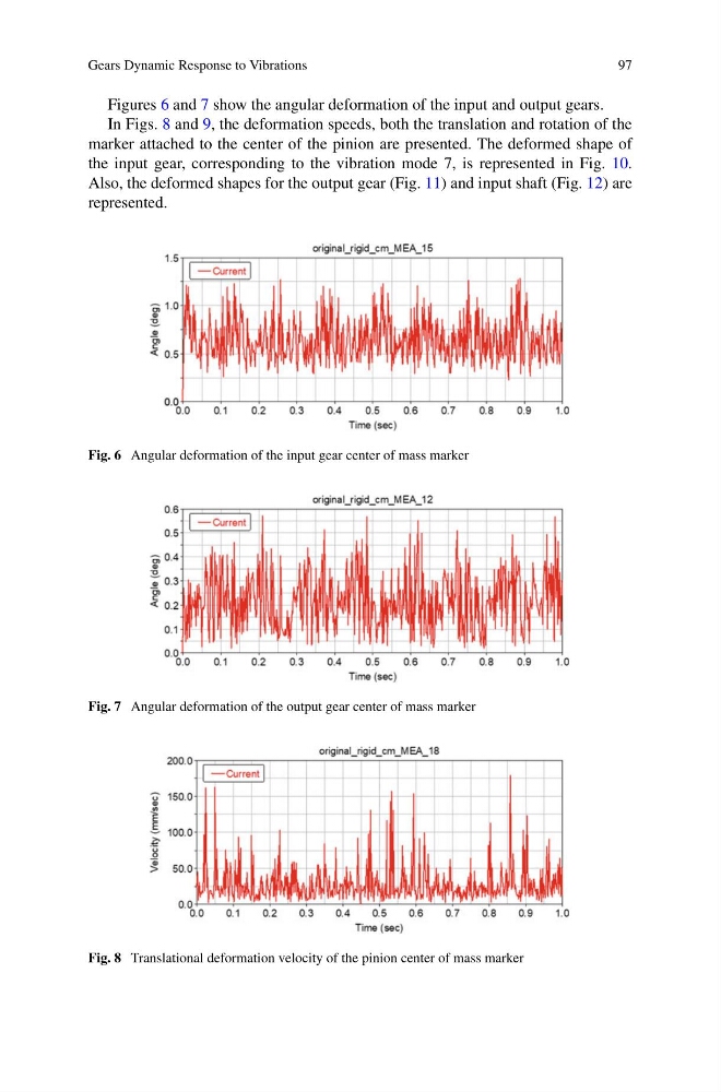
Figures 6 and 7 show the angular deformation of the input and output gears.
In Figs. 8 and 9, the deformation speeds, both the translation and rotation of the
marker attached to the center of the pinion are presented. The deformed shape of
the input gear, corresponding to the vibration mode 7, is represented in Fig. 10.
Also, the deformed shapes for the output gear (Fig. 11) and input shaft (Fig. 12) are
represented.
Fig. 6 Angular deformation of the input gear center of mass marker
Fig. 7 Angular deformation of the output gear center of mass marker
Fig. 8 Translational deformation velocity of the pinion center of mass marker
97
Figures 6 and 7 show the angular deformation of the input and output gears.
In Figs. 8 and 9, the deformation speeds, both the translation and rotation of the
marker attached to the center of the pinion are presented. The deformed shape of
the input gear, corresponding to the vibration mode 7, is represented in Fig. 10.
Also, the deformed shapes for the output gear (Fig. 11) and input shaft (Fig. 12) are
represented.
Fig. 6 Angular deformation of the input gear center of mass marker
Fig. 7 Angular deformation of the output gear center of mass marker
Fig. 8 Translational deformation velocity of the pinion center of mass marker