

Spatial rings and domes 71
profile of assembly is determined by the ratios given in Eqs (4.10) and
(4.16). It is in general unable to form a curved dome- like profile when
expanded because the newly created assembly is symmetric about its
middle plane on which the middle pivots of all the scissor- like elements lie
just like the individual rings. To form a proper dome, the outer loop must
differ in height from the inner loop, i.e. the loops need to become higher
and higher from the outer perimeter towards the centre. This can be
achieved by using an alterative type of intermediate tie.
4.3.2 Alternative intermediate tie
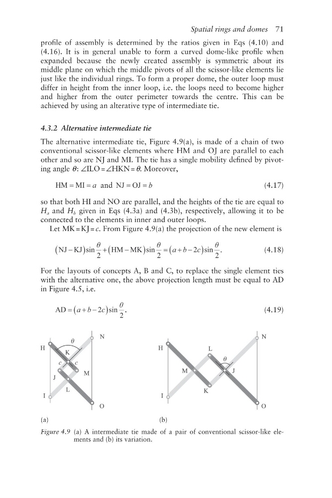
The alternative intermediate tie, Figure 4.9(a), is made of a chain of two
conventional scissor- like elements where HM and OJ are parallel to each
other and so are NJ and MI. The tie has a single mobility defined by pivoting angle θ : ∠ILO = ∠HKN = θ. Moreover,
and
(4.17)
so that both HI and NO are parallel, and the heights of the tie are equal to
H a and H b given in Eqs (4.3a) and (4.3b), respectively, allowing it to be
connected to the elements in inner and outer loops.
Let MK = KJ = c. From Figure 4.9(a) the projection of the new element is
.
(4.18)
For the layouts of concepts A, B and C, to replace the single element ties
with the alternative one, the above projection length must be equal to AD
in Figure 4.5, i.e.
.
(4.19)
(a)
(b)
Figure 4.9 (a) A intermediate tie made of a pair of conventional scissor-like elements and (b) its variation.
profile of assembly is determined by the ratios given in Eqs (4.10) and
(4.16). It is in general unable to form a curved dome- like profile when
expanded because the newly created assembly is symmetric about its
middle plane on which the middle pivots of all the scissor- like elements lie
just like the individual rings. To form a proper dome, the outer loop must
differ in height from the inner loop, i.e. the loops need to become higher
and higher from the outer perimeter towards the centre. This can be
achieved by using an alterative type of intermediate tie.
4.3.2 Alternative intermediate tie
The alternative intermediate tie, Figure 4.9(a), is made of a chain of two
conventional scissor- like elements where HM and OJ are parallel to each
other and so are NJ and MI. The tie has a single mobility defined by pivoting angle θ : ∠ILO = ∠HKN = θ. Moreover,
and
(4.17)
so that both HI and NO are parallel, and the heights of the tie are equal to
H a and H b given in Eqs (4.3a) and (4.3b), respectively, allowing it to be
connected to the elements in inner and outer loops.
Let MK = KJ = c. From Figure 4.9(a) the projection of the new element is
.
(4.18)
For the layouts of concepts A, B and C, to replace the single element ties
with the alternative one, the above projection length must be equal to AD
in Figure 4.5, i.e.
.
(4.19)
(a)
(b)
Figure 4.9 (a) A intermediate tie made of a pair of conventional scissor-like elements and (b) its variation.