

72 Spatial rings and domes
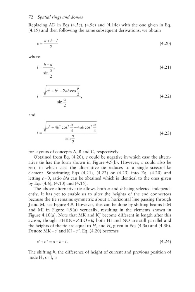
Replacing AD in Eqs (4.5c), (4.9c) and (4.14c) with the one given in Eq.
(4.19) and then following the same subsequent derivations, we obtain
(4.20)
where
,
(4.21)
,
(4.22)
and
(4.23)
for layouts of concepts A, B and C, respectively.
Obtained from Eq. (4.20), c could be negative in which case the alternative tie has the form shown in Figure 4.9(b). However, c could also be
zero in which case the alternative tie reduces to a single scissor- like
element. Substituting Eqs (4.21), (4.22) or (4.23) into Eq. (4.20) and
letting c = 0, ratio b/a can be obtained which is identical to the ones given
by Eqs (4.6), (4.10) and (4.15).
The above alternative tie allows both a and b being selected independently. It has yet to enable us to alter the heights of the end connectors
because the tie remains symmetric about a horizontal line passing through
J and M, see Figure 4.9. However, this can be done by shifting beams HM
and MI in Figure 4.9(a) vertically, resulting in the elements shown in
Figure 4.10(a). Note that MK and KJ become different in length after this
action, though ∠HKN = ∠ILO = θ, both HI and NO are still parallel and
the heights of the tie are equal to H a and H b given in Eqs (4.3a) and (4.3b).
Denote MK = c′ and KJ = c′′. Eq. (4.20) becomes
.
(4.24)
The shifting h, the difference of height of current and previous position of
node H, or I, is
Replacing AD in Eqs (4.5c), (4.9c) and (4.14c) with the one given in Eq.
(4.19) and then following the same subsequent derivations, we obtain
(4.20)
where
,
(4.21)
,
(4.22)
and
(4.23)
for layouts of concepts A, B and C, respectively.
Obtained from Eq. (4.20), c could be negative in which case the alternative tie has the form shown in Figure 4.9(b). However, c could also be
zero in which case the alternative tie reduces to a single scissor- like
element. Substituting Eqs (4.21), (4.22) or (4.23) into Eq. (4.20) and
letting c = 0, ratio b/a can be obtained which is identical to the ones given
by Eqs (4.6), (4.10) and (4.15).
The above alternative tie allows both a and b being selected independently. It has yet to enable us to alter the heights of the end connectors
because the tie remains symmetric about a horizontal line passing through
J and M, see Figure 4.9. However, this can be done by shifting beams HM
and MI in Figure 4.9(a) vertically, resulting in the elements shown in
Figure 4.10(a). Note that MK and KJ become different in length after this
action, though ∠HKN = ∠ILO = θ, both HI and NO are still parallel and
the heights of the tie are equal to H a and H b given in Eqs (4.3a) and (4.3b).
Denote MK = c′ and KJ = c′′. Eq. (4.20) becomes
.
(4.24)
The shifting h, the difference of height of current and previous position of
node H, or I, is