

Fundamental concepts 9
which corresponds to the retraction and expansion of the mirror
frame.
Some planar linkages have rigid links joined together to form a single
closed chain. In this situation, n = j, and thus at least four links (n = 4) are
needed to achieve mobility one (m = 1) according to Eq. (2.3). When the
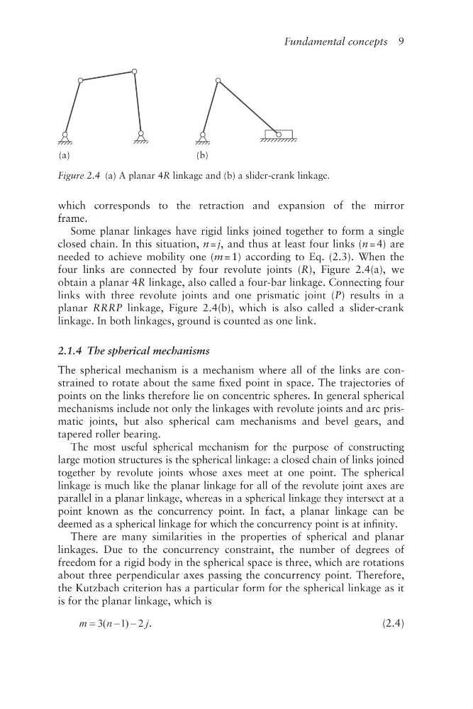
four links are connected by four revolute joints (R), Figure 2.4(a), we
obtain a planar 4R linkage, also called a four- bar linkage. Connecting four
links with three revolute joints and one prismatic joint (P) results in a
planar RRRP linkage, Figure 2.4(b), which is also called a slider- crank
linkage. In both linkages, ground is counted as one link.
2.1.4 The spherical mechanisms
The spherical mechanism is a mechanism where all of the links are constrained to rotate about the same fixed point in space. The trajectories of
points on the links therefore lie on concentric spheres. In general spherical
mechanisms include not only the linkages with revolute joints and arc prismatic joints, but also spherical cam mechanisms and bevel gears, and
tapered roller bearing.
The most useful spherical mechanism for the purpose of constructing
large motion structures is the spherical linkage: a closed chain of links joined
together by revolute joints whose axes meet at one point. The spherical
linkage is much like the planar linkage for all of the revolute joint axes are
parallel in a planar linkage, whereas in a spherical linkage they intersect at a
point known as the concurrency point. In fact, a planar linkage can be
deemed as a spherical linkage for which the concurrency point is at infinity.
There are many similarities in the properties of spherical and planar
linkages. Due to the concurrency constraint, the number of degrees of
freedom for a rigid body in the spherical space is three, which are rotations
about three perpendicular axes passing the concurrency point. Therefore,
the Kutzbach criterion has a particular form for the spherical linkage as it
is for the planar linkage, which is
.
(2.4)
(a)
(b)
Figure 2.4 (a) A planar 4R linkage and (b) a slider-crank linkage.
which corresponds to the retraction and expansion of the mirror
frame.
Some planar linkages have rigid links joined together to form a single
closed chain. In this situation, n = j, and thus at least four links (n = 4) are
needed to achieve mobility one (m = 1) according to Eq. (2.3). When the
four links are connected by four revolute joints (R), Figure 2.4(a), we
obtain a planar 4R linkage, also called a four- bar linkage. Connecting four
links with three revolute joints and one prismatic joint (P) results in a
planar RRRP linkage, Figure 2.4(b), which is also called a slider- crank
linkage. In both linkages, ground is counted as one link.
2.1.4 The spherical mechanisms
The spherical mechanism is a mechanism where all of the links are constrained to rotate about the same fixed point in space. The trajectories of
points on the links therefore lie on concentric spheres. In general spherical
mechanisms include not only the linkages with revolute joints and arc prismatic joints, but also spherical cam mechanisms and bevel gears, and
tapered roller bearing.
The most useful spherical mechanism for the purpose of constructing
large motion structures is the spherical linkage: a closed chain of links joined
together by revolute joints whose axes meet at one point. The spherical
linkage is much like the planar linkage for all of the revolute joint axes are
parallel in a planar linkage, whereas in a spherical linkage they intersect at a
point known as the concurrency point. In fact, a planar linkage can be
deemed as a spherical linkage for which the concurrency point is at infinity.
There are many similarities in the properties of spherical and planar
linkages. Due to the concurrency constraint, the number of degrees of
freedom for a rigid body in the spherical space is three, which are rotations
about three perpendicular axes passing the concurrency point. Therefore,
the Kutzbach criterion has a particular form for the spherical linkage as it
is for the planar linkage, which is
.
(2.4)
(a)
(b)
Figure 2.4 (a) A planar 4R linkage and (b) a slider-crank linkage.