

The Bennett linkage 105
etc. represent the projection of X, R and Z on the plane x′o′y′, etc. The
design parameters ω, λ and L are clearly shown in Figure 5.17(b).
Assume
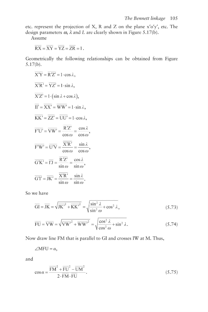
.
Geometrically the following relationships can be obtained from Figure
5.17(b).
,
,
,
,
,
,
,
,
.
So we have
,
(5.73)
.
(5.74)
Now draw line FM that is parallel to GI and crosses IW at M. Thus,
,
and
.
(5.75)
etc. represent the projection of X, R and Z on the plane x′o′y′, etc. The
design parameters ω, λ and L are clearly shown in Figure 5.17(b).
Assume
.
Geometrically the following relationships can be obtained from Figure
5.17(b).
,
,
,
,
,
,
,
,
.
So we have
,
(5.73)
.
(5.74)
Now draw line FM that is parallel to GI and crosses IW at M. Thus,
,
and
.
(5.75)