

104 The Bennett linkage
through FH and axis y through EG. The linkage EFGH is therefore symmetric about both xoz and yoz planes where o is the centre of EFGH and
axis z is perpendicular to plane xoy. Now introduce a square bar, shown
in light grey colour in Figure 5.16(b), to replace link FG in such a way that
one of the edges of the square bar lies along FG. The bar is terminated by
planes GIJK and FUVW, created by slicing the bar by the plane yoz and
xoz, respectively. This bar is one of the rods in the model shown in Figure
5.15.
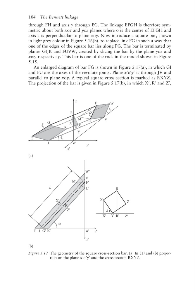
An enlarged diagram of bar FG is shown in Figure 5.17(a), in which GI
and FU are the axes of the revolute joints. Plane x′o′y′ is through JV and
parallel to plane xoy. A typical square cross- section is marked as RXYZ.
The projection of the bar is given in Figure 5.17(b), in which X′, R′ and Z′,
(a)
(b)
Figure 5.17 The geometry of the square cross-section bar. (a) In 3D and (b) projection on the plane x'o'y' and the cross-section RXYZ.
through FH and axis y through EG. The linkage EFGH is therefore symmetric about both xoz and yoz planes where o is the centre of EFGH and
axis z is perpendicular to plane xoy. Now introduce a square bar, shown
in light grey colour in Figure 5.16(b), to replace link FG in such a way that
one of the edges of the square bar lies along FG. The bar is terminated by
planes GIJK and FUVW, created by slicing the bar by the plane yoz and
xoz, respectively. This bar is one of the rods in the model shown in Figure
5.15.
An enlarged diagram of bar FG is shown in Figure 5.17(a), in which GI
and FU are the axes of the revolute joints. Plane x′o′y′ is through JV and
parallel to plane xoy. A typical square cross- section is marked as RXYZ.
The projection of the bar is given in Figure 5.17(b), in which X′, R′ and Z′,
(a)
(b)
Figure 5.17 The geometry of the square cross-section bar. (a) In 3D and (b) projection on the plane x'o'y' and the cross-section RXYZ.