

4.3 Results and Discussion
107
4.3.3 Modelling Larger Pulsed Beds Using Two-Fluid Models
The remarkable difference between the two predicted flows highlights the significance of frictional stress to these structured flows. However, in order to further
verify that if the incorrect pattern is associated with the artificially small domain, the
two-fluid model is put into a test of modelling structured bubbles in a larger domain.
The experimental conditions for producing flow patterns are taken from Regelink’s
work [41]. The experiments were conducted in a 40 × 1.5 cm quasi-2D bed of sand
particles fluidised under ambient conditions. The particles have a size distribution
of 230–590 μm and an average size of 360 μm. The experimentally measured U mf
was 0.13 m/s. The static bed height was approximately 40 cm. The experimentally
measured voidage at minimum fluidisation E mf is unknown, and, instead, frictional
packing limit φ f is chosen carefully to approximate the experimentally measured
U mf . The calculation showed that a value of φ f = 0.6 yields a numerical U mf of
0.11 m/s. The slight difference between predicted and experimental U mf could be
attributed to the polydispersity and shape factor.
To simulate the larger pulsed beds, 2D TFM simulations are carried out with
the same type of closures and boundary conditions, as listed in Tables 4.3 and 4.5,
for consistency. A sensitivity analysis is conducted to refine the time step and grid
size. Time steps of 5 × 10
−4 and 1 × 10
−4 s, and grid sizes of 2 and 5 mm exhibit
no substantial differences in time-average bubble size profile and bed expansion.
Therefore, grids of uniform 5 mm square cells and a time step of 5 × 10
−4 s are
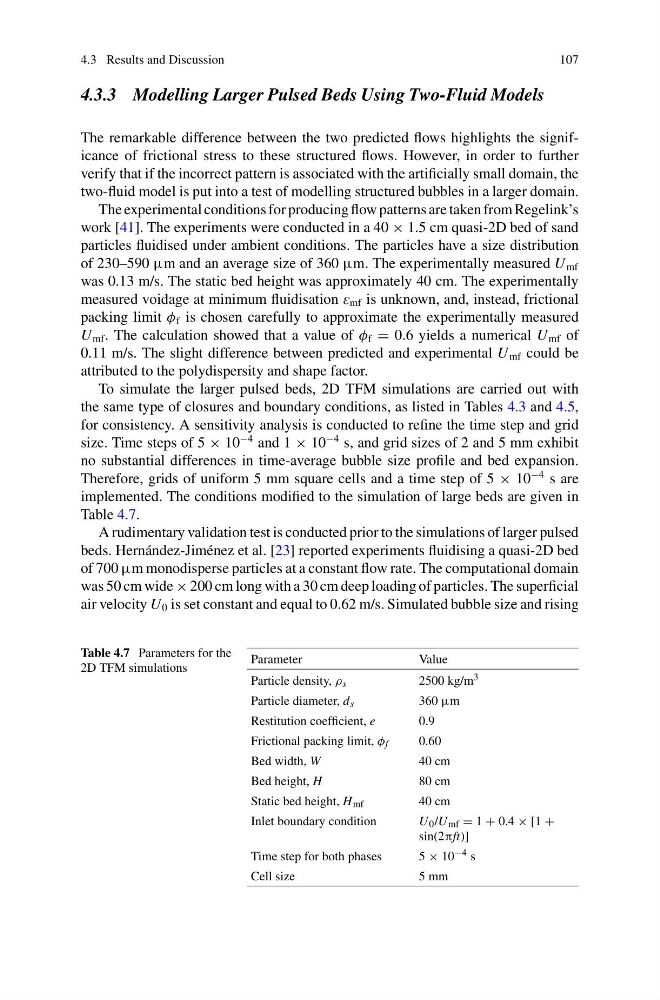
implemented. The conditions modified to the simulation of large beds are given in
Table 4.7.
A rudimentary validation test is conducted prior to the simulations of larger pulsed
beds. Hernández-Jiménez et al. [23] reported experiments fluidising a quasi-2D bed
of 700 μm monodisperse particles at a constant flow rate. The computational domain
was 50 cm wide × 200 cm long with a 30 cm deep loading of particles. The superficial
air velocity U 0 is set constant and equal to 0.62 m/s. Simulated bubble size and rising
Table 4.7 Parameters for the
2D TFM simulations
Parameter
Value
Particle density, ρ s
2500 kg/m 3
Particle diameter, d s
360 μm
Restitution coefficient, e
0.9
Frictional packing limit, φ f
0.60
Bed width, W
40 cm
Bed height, H
80 cm
Static bed height, H mf
40 cm
Inlet boundary condition
U 0 /U mf = 1 + 0.4 × [1 +
sin(2πft)]
Time step for both phases
5 × 10 −4 s
Cell size
5 mm
107
4.3.3 Modelling Larger Pulsed Beds Using Two-Fluid Models
The remarkable difference between the two predicted flows highlights the significance of frictional stress to these structured flows. However, in order to further
verify that if the incorrect pattern is associated with the artificially small domain, the
two-fluid model is put into a test of modelling structured bubbles in a larger domain.
The experimental conditions for producing flow patterns are taken from Regelink’s
work [41]. The experiments were conducted in a 40 × 1.5 cm quasi-2D bed of sand
particles fluidised under ambient conditions. The particles have a size distribution
of 230–590 μm and an average size of 360 μm. The experimentally measured U mf
was 0.13 m/s. The static bed height was approximately 40 cm. The experimentally
measured voidage at minimum fluidisation E mf is unknown, and, instead, frictional
packing limit φ f is chosen carefully to approximate the experimentally measured
U mf . The calculation showed that a value of φ f = 0.6 yields a numerical U mf of
0.11 m/s. The slight difference between predicted and experimental U mf could be
attributed to the polydispersity and shape factor.
To simulate the larger pulsed beds, 2D TFM simulations are carried out with
the same type of closures and boundary conditions, as listed in Tables 4.3 and 4.5,
for consistency. A sensitivity analysis is conducted to refine the time step and grid
size. Time steps of 5 × 10
−4 and 1 × 10
−4 s, and grid sizes of 2 and 5 mm exhibit
no substantial differences in time-average bubble size profile and bed expansion.
Therefore, grids of uniform 5 mm square cells and a time step of 5 × 10
−4 s are
implemented. The conditions modified to the simulation of large beds are given in
Table 4.7.
A rudimentary validation test is conducted prior to the simulations of larger pulsed
beds. Hernández-Jiménez et al. [23] reported experiments fluidising a quasi-2D bed
of 700 μm monodisperse particles at a constant flow rate. The computational domain
was 50 cm wide × 200 cm long with a 30 cm deep loading of particles. The superficial
air velocity U 0 is set constant and equal to 0.62 m/s. Simulated bubble size and rising
Table 4.7 Parameters for the
2D TFM simulations
Parameter
Value
Particle density, ρ s
2500 kg/m 3
Particle diameter, d s
360 μm
Restitution coefficient, e
0.9
Frictional packing limit, φ f
0.60
Bed width, W
40 cm
Bed height, H
80 cm
Static bed height, H mf
40 cm
Inlet boundary condition
U 0 /U mf = 1 + 0.4 × [1 +
sin(2πft)]
Time step for both phases
5 × 10 −4 s
Cell size
5 mm