

1 Single Nanomagnet Behaviour: Surface and Finite-Size Effects
29
-4 -3 -2 -1 0 1 2 3 4
h (K)
-0.4
-0.2
0.0
0.2
0.4
0.6
M
Total
-4 -3 -2 -1 0 1 2 3 4
h (K)
-0.2
0.0
0.1
M
Sh
Int
ZFC
FC
(b)
(a)
ZFC
FC
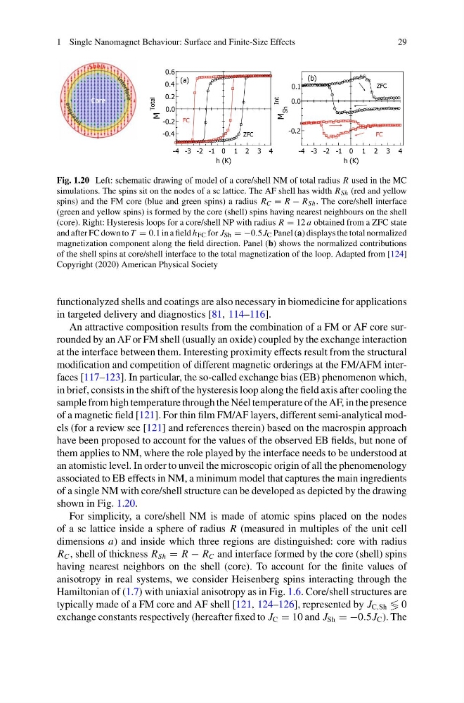
Fig. 1.20 Left: schematic drawing of model of a core/shell NM of total radius R used in the MC
simulations. The spins sit on the nodes of a sc lattice. The AF shell has width R Sh (red and yellow
spins) and the FM core (blue and green spins) a radius R C = R − R Sh . The core/shell interface
(green and yellow spins) is formed by the core (shell) spins having nearest neighbours on the shell
(core). Right: Hysteresis loops for a core/shell NP with radius R = 12 a obtained from a ZFC state
and after FC down to T = 0.1 in a field h FC for J Sh = −0.5J C Panel (a) displays the total normalized
magnetization component along the field direction. Panel (b) shows the normalized contributions
of the shell spins at core/shell interface to the total magnetization of the loop. Adapted from [124]
Copyright (2020) American Physical Society
functionalyzed shells and coatings are also necessary in biomedicine for applications
in targeted delivery and diagnostics [81, 114–116].
An attractive composition results from the combination of a FM or AF core surrounded by an AF or FM shell (usually an oxide) coupled by the exchange interaction
at the interface between them. Interesting proximity effects result from the structural
modification and competition of different magnetic orderings at the FM/AFM interfaces [117–123]. In particular, the so-called exchange bias (EB) phenomenon which,
in brief, consists in the shift of the hysteresis loop along the field axis after cooling the
sample from high temperature through the Néel temperature of the AF, in the presence
of a magnetic field [121]. For thin film FM/AF layers, different semi-analytical models (for a review see [121] and references therein) based on the macrospin approach
have been proposed to account for the values of the observed EB fields, but none of
them applies to NM, where the role played by the interface needs to be understood at
an atomistic level. In order to unveil the microscopic origin of all the phenomenology
associated to EB effects in NM, a minimum model that captures the main ingredients
of a single NM with core/shell structure can be developed as depicted by the drawing
shown in Fig. 1.20.
For simplicity, a core/shell NM is made of atomic spins placed on the nodes
of a sc lattice inside a sphere of radius R (measured in multiples of the unit cell
dimensions a) and inside which three regions are distinguished: core with radius
R C , shell of thickness R Sh = R − R C and interface formed by the core (shell) spins
having nearest neighbors on the shell (core). To account for the finite values of
anisotropy in real systems, we consider Heisenberg spins interacting through the
Hamiltonian of (1.7) with uniaxial anisotropy as in Fig. 1.6. Core/shell structures are
typically made of a FM core and AF shell [121, 124–126], represented by J C,Sh ≶ 0
exchange constants respectively (hereafter fixed to J C = 10 and J Sh = −0.5J C ). The
29
-4 -3 -2 -1 0 1 2 3 4
h (K)
-0.4
-0.2
0.0
0.2
0.4
0.6
M
Total
-4 -3 -2 -1 0 1 2 3 4
h (K)
-0.2
0.0
0.1
M
Sh
Int
ZFC
FC
(b)
(a)
ZFC
FC
Fig. 1.20 Left: schematic drawing of model of a core/shell NM of total radius R used in the MC
simulations. The spins sit on the nodes of a sc lattice. The AF shell has width R Sh (red and yellow
spins) and the FM core (blue and green spins) a radius R C = R − R Sh . The core/shell interface
(green and yellow spins) is formed by the core (shell) spins having nearest neighbours on the shell
(core). Right: Hysteresis loops for a core/shell NP with radius R = 12 a obtained from a ZFC state
and after FC down to T = 0.1 in a field h FC for J Sh = −0.5J C Panel (a) displays the total normalized
magnetization component along the field direction. Panel (b) shows the normalized contributions
of the shell spins at core/shell interface to the total magnetization of the loop. Adapted from [124]
Copyright (2020) American Physical Society
functionalyzed shells and coatings are also necessary in biomedicine for applications
in targeted delivery and diagnostics [81, 114–116].
An attractive composition results from the combination of a FM or AF core surrounded by an AF or FM shell (usually an oxide) coupled by the exchange interaction
at the interface between them. Interesting proximity effects result from the structural
modification and competition of different magnetic orderings at the FM/AFM interfaces [117–123]. In particular, the so-called exchange bias (EB) phenomenon which,
in brief, consists in the shift of the hysteresis loop along the field axis after cooling the
sample from high temperature through the Néel temperature of the AF, in the presence
of a magnetic field [121]. For thin film FM/AF layers, different semi-analytical models (for a review see [121] and references therein) based on the macrospin approach
have been proposed to account for the values of the observed EB fields, but none of
them applies to NM, where the role played by the interface needs to be understood at
an atomistic level. In order to unveil the microscopic origin of all the phenomenology
associated to EB effects in NM, a minimum model that captures the main ingredients
of a single NM with core/shell structure can be developed as depicted by the drawing
shown in Fig. 1.20.
For simplicity, a core/shell NM is made of atomic spins placed on the nodes
of a sc lattice inside a sphere of radius R (measured in multiples of the unit cell
dimensions a) and inside which three regions are distinguished: core with radius
R C , shell of thickness R Sh = R − R C and interface formed by the core (shell) spins
having nearest neighbors on the shell (core). To account for the finite values of
anisotropy in real systems, we consider Heisenberg spins interacting through the
Hamiltonian of (1.7) with uniaxial anisotropy as in Fig. 1.6. Core/shell structures are
typically made of a FM core and AF shell [121, 124–126], represented by J C,Sh ≶ 0
exchange constants respectively (hereafter fixed to J C = 10 and J Sh = −0.5J C ). The