

13 Magnetic Nanoparticles for Life Sciences Applications
309
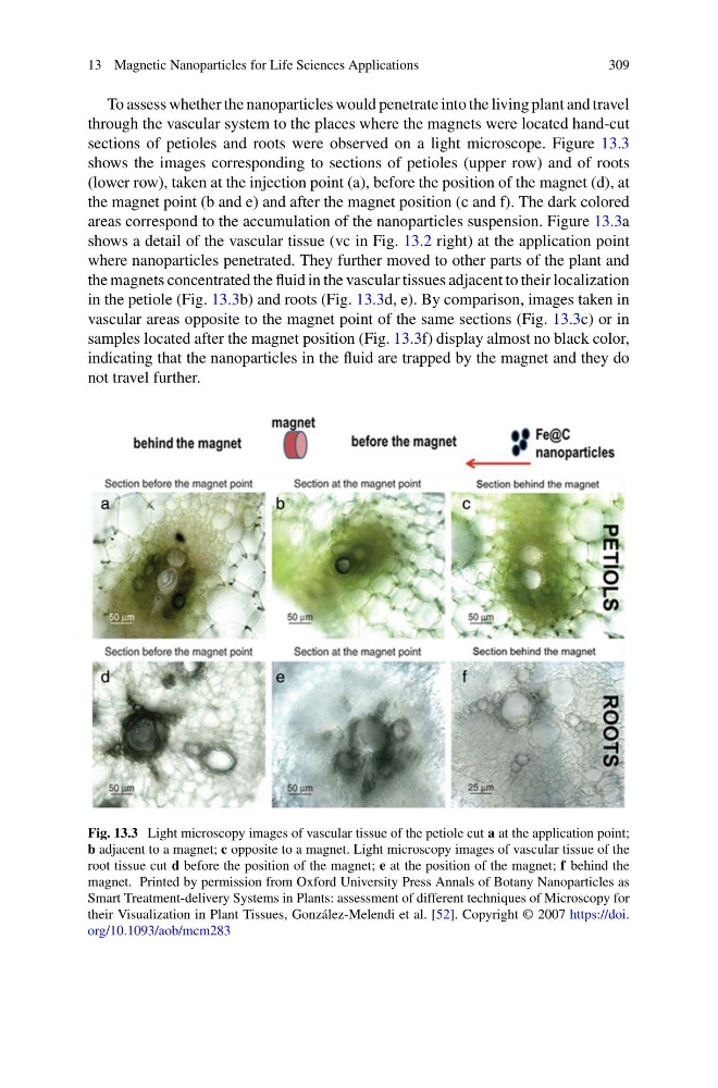
To assess whether the nanoparticles would penetrate into the living plant and travel
through the vascular system to the places where the magnets were located hand-cut
sections of petioles and roots were observed on a light microscope. Figure 13.3
shows the images corresponding to sections of petioles (upper row) and of roots
(lower row), taken at the injection point (a), before the position of the magnet (d), at
the magnet point (b and e) and after the magnet position (c and f). The dark colored
areas correspond to the accumulation of the nanoparticles suspension. Figure 13.3a
shows a detail of the vascular tissue (vc in Fig. 13.2 right) at the application point
where nanoparticles penetrated. They further moved to other parts of the plant and
the magnets concentrated the fluid in the vascular tissues adjacent to their localization
in the petiole (Fig. 13.3b) and roots (Fig. 13.3d, e). By comparison, images taken in
vascular areas opposite to the magnet point of the same sections (Fig. 13.3c) or in
samples located after the magnet position (Fig. 13.3f) display almost no black color,
indicating that the nanoparticles in the fluid are trapped by the magnet and they do
not travel further.
Fig. 13.3 Light microscopy images of vascular tissue of the petiole cut a at the application point;
b adjacent to a magnet; c opposite to a magnet. Light microscopy images of vascular tissue of the
root tissue cut d before the position of the magnet; e at the position of the magnet; f behind the
magnet. Printed by permission from Oxford University Press Annals of Botany Nanoparticles as
Smart Treatment-delivery Systems in Plants: assessment of different techniques of Microscopy for
their Visualization in Plant Tissues, González-Melendi et al. [52]. Copyright © 2007 https://doi.
org/10.1093/aob/mcm283
309
To assess whether the nanoparticles would penetrate into the living plant and travel
through the vascular system to the places where the magnets were located hand-cut
sections of petioles and roots were observed on a light microscope. Figure 13.3
shows the images corresponding to sections of petioles (upper row) and of roots
(lower row), taken at the injection point (a), before the position of the magnet (d), at
the magnet point (b and e) and after the magnet position (c and f). The dark colored
areas correspond to the accumulation of the nanoparticles suspension. Figure 13.3a
shows a detail of the vascular tissue (vc in Fig. 13.2 right) at the application point
where nanoparticles penetrated. They further moved to other parts of the plant and
the magnets concentrated the fluid in the vascular tissues adjacent to their localization
in the petiole (Fig. 13.3b) and roots (Fig. 13.3d, e). By comparison, images taken in
vascular areas opposite to the magnet point of the same sections (Fig. 13.3c) or in
samples located after the magnet position (Fig. 13.3f) display almost no black color,
indicating that the nanoparticles in the fluid are trapped by the magnet and they do
not travel further.
Fig. 13.3 Light microscopy images of vascular tissue of the petiole cut a at the application point;
b adjacent to a magnet; c opposite to a magnet. Light microscopy images of vascular tissue of the
root tissue cut d before the position of the magnet; e at the position of the magnet; f behind the
magnet. Printed by permission from Oxford University Press Annals of Botany Nanoparticles as
Smart Treatment-delivery Systems in Plants: assessment of different techniques of Microscopy for
their Visualization in Plant Tissues, González-Melendi et al. [52]. Copyright © 2007 https://doi.
org/10.1093/aob/mcm283