

3 Percolation Toward Lateral Junctions
51
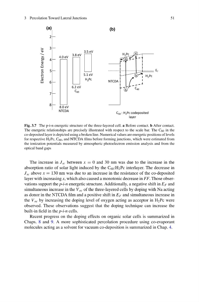
Fig. 3.7 The p-i-n energetic structure of the three-layered cell. a Before contact. b After contact.
The energetic relationships are precisely illustrated with respect to the scale bar. The C 60 in the
co-deposited layer is depicted using a broken line. Numerical values are energetic positions of levels
for respective H 2 Pc, C 60 , and NTCDA films before forming junctions, which were estimated from
the ionization potentials measured by atmospheric photoelectron emission analysis and from the
optical band gaps
The increase in J sc between x = 0 and 30 nm was due to the increase in the
absorption ratio of solar light induced by the C 60 :H 2 Pc interlayer. The decrease in
J sc above x = 130 nm was due to an increase in the resistance of the co-deposited
layer with increasing x, which also caused a monotonic decrease in FF. Those observations support the p-i-n energetic structure. Additionally, a negative shift in E F and
simultaneous increase in the V oc of the three-layered cells by doping with Na acting
as donor in the NTCDA film and a positive shift in E F and simultaneous increase in
the V oc by increasing the doping level of oxygen acting as acceptor in H 2 Pc were
observed. These observations suggest that the doping technique can increase the
built-in field in the p-i-n cells.
Recent progress on the doping effects on organic solar cells is summarized in
Chaps. 8 and 9. A more sophisticated percolation procedure using co-evaporant
molecules acting as a solvent for vacuum co-deposition is summarized in Chap. 4.
51
Fig. 3.7 The p-i-n energetic structure of the three-layered cell. a Before contact. b After contact.
The energetic relationships are precisely illustrated with respect to the scale bar. The C 60 in the
co-deposited layer is depicted using a broken line. Numerical values are energetic positions of levels
for respective H 2 Pc, C 60 , and NTCDA films before forming junctions, which were estimated from
the ionization potentials measured by atmospheric photoelectron emission analysis and from the
optical band gaps
The increase in J sc between x = 0 and 30 nm was due to the increase in the
absorption ratio of solar light induced by the C 60 :H 2 Pc interlayer. The decrease in
J sc above x = 130 nm was due to an increase in the resistance of the co-deposited
layer with increasing x, which also caused a monotonic decrease in FF. Those observations support the p-i-n energetic structure. Additionally, a negative shift in E F and
simultaneous increase in the V oc of the three-layered cells by doping with Na acting
as donor in the NTCDA film and a positive shift in E F and simultaneous increase in
the V oc by increasing the doping level of oxygen acting as acceptor in H 2 Pc were
observed. These observations suggest that the doping technique can increase the
built-in field in the p-i-n cells.
Recent progress on the doping effects on organic solar cells is summarized in
Chaps. 8 and 9. A more sophisticated percolation procedure using co-evaporant
molecules acting as a solvent for vacuum co-deposition is summarized in Chap. 4.