

2 A Path to the Blended Junction
39
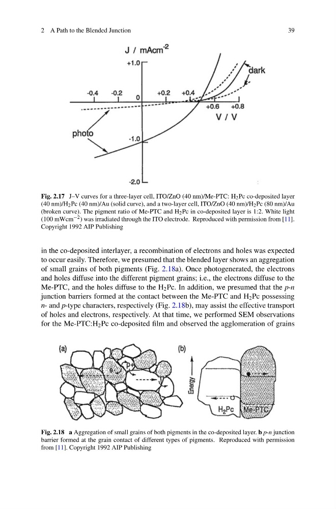
Fig. 2.17 J–V curves for a three-layer cell, ITO/ZnO (40 nm)/Me-PTC: H 2 Pc co-deposited layer
(40 nm)/H 2 Pc (40 nm)/Au (solid curve), and a two-layer cell, ITO/ZnO (40 nm)/H 2 Pc (80 nm)/Au
(broken curve). The pigment ratio of Me-PTC and H 2 Pc in co-deposited layer is 1:2. White light
(100 mWcm −2 ) was irradiated through the ITO electrode. Reproduced with permission from [11].
Copyright 1992 AIP Publishing
in the co-deposited interlayer, a recombination of electrons and holes was expected
to occur easily. Therefore, we presumed that the blended layer shows an aggregation
of small grains of both pigments (Fig. 2.18a). Once photogenerated, the electrons
and holes diffuse into the different pigment grains; i.e., the electrons diffuse to the
Me-PTC, and the holes diffuse to the H 2 Pc. In addition, we presumed that the p-n
junction barriers formed at the contact between the Me-PTC and H 2 Pc possessing
n- and p-type characters, respectively (Fig. 2.18b), may assist the effective transport
of holes and electrons, respectively. At that time, we performed SEM observations
for the Me-PTC:H 2 Pc co-deposited film and observed the agglomeration of grains
Fig. 2.18 a Aggregation of small grains of both pigments in the co-deposited layer. b p-n junction
barrier formed at the grain contact of different types of pigments. Reproduced with permission
from [11]. Copyright 1992 AIP Publishing
39
Fig. 2.17 J–V curves for a three-layer cell, ITO/ZnO (40 nm)/Me-PTC: H 2 Pc co-deposited layer
(40 nm)/H 2 Pc (40 nm)/Au (solid curve), and a two-layer cell, ITO/ZnO (40 nm)/H 2 Pc (80 nm)/Au
(broken curve). The pigment ratio of Me-PTC and H 2 Pc in co-deposited layer is 1:2. White light
(100 mWcm −2 ) was irradiated through the ITO electrode. Reproduced with permission from [11].
Copyright 1992 AIP Publishing
in the co-deposited interlayer, a recombination of electrons and holes was expected
to occur easily. Therefore, we presumed that the blended layer shows an aggregation
of small grains of both pigments (Fig. 2.18a). Once photogenerated, the electrons
and holes diffuse into the different pigment grains; i.e., the electrons diffuse to the
Me-PTC, and the holes diffuse to the H 2 Pc. In addition, we presumed that the p-n
junction barriers formed at the contact between the Me-PTC and H 2 Pc possessing
n- and p-type characters, respectively (Fig. 2.18b), may assist the effective transport
of holes and electrons, respectively. At that time, we performed SEM observations
for the Me-PTC:H 2 Pc co-deposited film and observed the agglomeration of grains
Fig. 2.18 a Aggregation of small grains of both pigments in the co-deposited layer. b p-n junction
barrier formed at the grain contact of different types of pigments. Reproduced with permission
from [11]. Copyright 1992 AIP Publishing