

34
M. Hiramoto
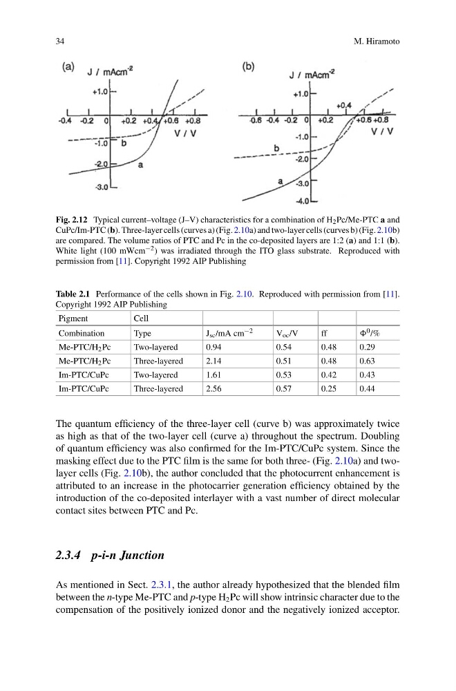
Fig. 2.12 Typical current–voltage (J–V) characteristics for a combination of H 2 Pc/Me-PTC a and
CuPc/Im-PTC (b). Three-layer cells (curves a) (Fig. 2.10a) and two-layer cells (curves b) (Fig. 2.10b)
are compared. The volume ratios of PTC and Pc in the co-deposited layers are 1:2 (a) and 1:1 (b).
White light (100 mWcm −2 ) was irradiated through the ITO glass substrate. Reproduced with
permission from [11]. Copyright 1992 AIP Publishing
Table 2.1 Performance of the cells shown in Fig. 2.10. Reproduced with permission from [11].
Copyright 1992 AIP Publishing
Pigment
Cell
Combination
Type
J sc /mA cm −2
V oc /V
ff
0 /%
Me-PTC/H 2 Pc
Two-layered
0.94
0.54
0.48
0.29
Me-PTC/H 2 Pc
Three-layered
2.14
0.51
0.48
0.63
Im-PTC/CuPc
Two-layered
1.61
0.53
0.42
0.43
Im-PTC/CuPc
Three-layered
2.56
0.57
0.25
0.44
The quantum efficiency of the three-layer cell (curve b) was approximately twice
as high as that of the two-layer cell (curve a) throughout the spectrum. Doubling
of quantum efficiency was also confirmed for the Im-PTC/CuPc system. Since the
masking effect due to the PTC film is the same for both three- (Fig. 2.10a) and twolayer cells (Fig. 2.10b), the author concluded that the photocurrent enhancement is
attributed to an increase in the photocarrier generation efficiency obtained by the
introduction of the co-deposited interlayer with a vast number of direct molecular
contact sites between PTC and Pc.
2.3.4 p-i-n Junction
As mentioned in Sect. 2.3.1, the author already hypothesized that the blended film
between the n-type Me-PTC and p-type H 2 Pc will show intrinsic character due to the
compensation of the positively ionized donor and the negatively ionized acceptor.
M. Hiramoto
Fig. 2.12 Typical current–voltage (J–V) characteristics for a combination of H 2 Pc/Me-PTC a and
CuPc/Im-PTC (b). Three-layer cells (curves a) (Fig. 2.10a) and two-layer cells (curves b) (Fig. 2.10b)
are compared. The volume ratios of PTC and Pc in the co-deposited layers are 1:2 (a) and 1:1 (b).
White light (100 mWcm −2 ) was irradiated through the ITO glass substrate. Reproduced with
permission from [11]. Copyright 1992 AIP Publishing
Table 2.1 Performance of the cells shown in Fig. 2.10. Reproduced with permission from [11].
Copyright 1992 AIP Publishing
Pigment
Cell
Combination
Type
J sc /mA cm −2
V oc /V
ff
0 /%
Me-PTC/H 2 Pc
Two-layered
0.94
0.54
0.48
0.29
Me-PTC/H 2 Pc
Three-layered
2.14
0.51
0.48
0.63
Im-PTC/CuPc
Two-layered
1.61
0.53
0.42
0.43
Im-PTC/CuPc
Three-layered
2.56
0.57
0.25
0.44
The quantum efficiency of the three-layer cell (curve b) was approximately twice
as high as that of the two-layer cell (curve a) throughout the spectrum. Doubling
of quantum efficiency was also confirmed for the Im-PTC/CuPc system. Since the
masking effect due to the PTC film is the same for both three- (Fig. 2.10a) and twolayer cells (Fig. 2.10b), the author concluded that the photocurrent enhancement is
attributed to an increase in the photocarrier generation efficiency obtained by the
introduction of the co-deposited interlayer with a vast number of direct molecular
contact sites between PTC and Pc.
2.3.4 p-i-n Junction
As mentioned in Sect. 2.3.1, the author already hypothesized that the blended film
between the n-type Me-PTC and p-type H 2 Pc will show intrinsic character due to the
compensation of the positively ionized donor and the negatively ionized acceptor.